Guild icon
wafer.space Community
ℹ️ - Information / general
Welcome to wafer.space - documentation at wafer.space github - buy at buy.wafer.space - archives at discord.wafer.space
Between 2026-05-31 11:59 p.m. and 2026-07-01 12:00 a.m.

Avatar
Helo (edited)
👋 2
Avatar
@Leo Moser (mole99) @Tim 'mithro' Ansell Spammer to ban ...
Avatar
Avatar
ewen
https://support.discord.com/hc/en-us/articles/205369668-How-do-I-set-up-a-Role-Exclusive-announcements-channel Tl;DR: set up group of users who are to have permissions to post announcements, change channel permissions to remove "send message" from the "Everyone" group, and add "send message" permission for the group of users that should be allowed to post.
^^^^ perhaps it'd be a good idea to limit who can post to #welcome-and-rules, #announcements etc, so that at least the spam doesn't end up there? (Howto link in the message I'm replying to, from February 2026.)
💯 2
Avatar
Avatar
tnt
@Leo Moser (mole99) @Tim 'mithro' Ansell Spammer to ban ...
Leo Moser (mole99) 2026-06-03 9:58 a.m.
Thanks
Avatar
Avatar
ewen
^^^^ perhaps it'd be a good idea to limit who can post to #welcome-and-rules, #announcements etc, so that at least the spam doesn't end up there? (Howto link in the message I'm replying to, from February 2026.)
Leo Moser (mole99) 2026-06-03 9:58 a.m.
@Tim 'mithro' Ansell
Avatar
Avatar
ewen
https://support.discord.com/hc/en-us/articles/205369668-How-do-I-set-up-a-Role-Exclusive-announcements-channel Tl;DR: set up group of users who are to have permissions to post announcements, change channel permissions to remove "send message" from the "Everyone" group, and add "send message" permission for the group of users that should be allowed to post.
Tim 'mithro' Ansell 2026-06-04 12:08 a.m.
I think I've make that happen for the #welcome-and-rules and #announcements channels now?
Avatar
Tim 'mithro' Ansell 2026-06-04 12:52 a.m.
@Noritsuna Imamura - Cool to see you updated the repo @ https://github.com/ishi-kai/ISHI-KAI_Multiple_Projects_WaferSapce-GF180-1 with pictures of the real die!
ISHI-KAI's Multiple Projects Wafer for Wafer.Sapce GF180 Run 1. - ishi-kai/ISHI-KAI_Multiple_Projects_WaferSapce-GF180-1
😎 2
💜 1
Avatar
Avatar
Tim 'mithro' Ansell
I think I've make that happen for the #welcome-and-rules and #announcements channels now?
LGTM. In #welcome-and-rules I now see "you do not have permission to post" and in #announcements I see "follow for updates in your server" (which is the normal "this is a read-only announcements channel). Thanks for sorting that out.
Avatar
I had a bit of an idea
Avatar
What was the max ram/cache we can have?
Avatar
A full die* with the new (untested) 3v3 SRAM is like 44-54 KB depending on how much padding you include for routing.. The 5v SRAM is like 21-24 KB iirc *inside the pad ring. You can probably fit more with a custom pad ring. (edited)
5:05 p.m.
(and that's the entire usable die area filled with sram macros, and basically no space for logic)
Avatar
Ok. So still too small for full addressing of a 6502(64k)
5:20 a.m.
Im wanting to test something like, a 'minicpu' spaced every few hundred MB of RAM
Avatar
Can we have dram? Would we get more?
5:43 a.m.
I guess sram is better... And I could structure a 6502 core to use a large amount of on die ram cache, and still use external address space. Not sure yet. I guess the ram makers have their own tricks
Avatar
Avatar
Wayfarer
Can we have dram? Would we get more?
Tim 'mithro' Ansell 2026-06-06 6:53 a.m.
Using external COTS PSRAM is probably the easist option. Atleast one person has done a external SRAM interface.
Avatar
Yeah PSRAM and "HyperRAM"/octal PSRAM should be pretty straightforward. They are all SPI, QuadSPI or a small parallel interface. I was looking at SDRAM chips but the need like 50 pins and are much more involved with refreshes and such
Avatar
Leo Moser (mole99) 2026-06-06 3:51 p.m.
👍 1
Avatar
Avatar
Tim 'mithro' Ansell
Using external COTS PSRAM is probably the easist option. Atleast one person has done a external SRAM interface.
Thanks, the notion is a "minicpu" every few MB of RAM, so a massively distributed system across a multi GB array. Prototyping this at small scale may be advantageous. My other notion is to put a 6502, 6522 and a ton of cache on a single die. Then have external connections to other memory and devices. (Mmio based architecture)
2:27 a.m.
I think I'll focus on the later for now, as well as my "geometric" computer/coprocessor.
2:27 a.m.
Thanks
Avatar
So, because a 6502 with megabytes of ram is impractical at this point, I'm going to focus on a math coprocessor for the 6502 family.
4:28 p.m.
I also have an isa bus dma control chip I'm working on. If there is volume, can we get a discount?
4:30 p.m.
Oh. You get 1000 chips here. Ok.
4:30 p.m.
That actually works out to less than $10 a chip yeah?
4:31 p.m.
So totally worth a crowd funding campaign. And a 6502 math coprocessor would probably sell well
Avatar
Avatar
Wayfarer
So totally worth a crowd funding campaign. And a 6502 math coprocessor would probably sell well
You're not gonna crowd fund your first ASIC tapeout with that as the goal.
👍 1
Avatar
Avatar
namibj
You're not gonna crowd fund your first ASIC tapeout with that as the goal.
You seem confident in this statement.
4:44 p.m.
I don't appreciate the discouraging words. Take care.
Avatar
The problem is that testing is HARD and without experience the risk of the dies being DoA is substantial. And in that scenario it'd be the crowd that suffers. If you can use appropriate techniques to mitigate that risk it'd be fine.
Avatar
Avatar
Wayfarer
I don't appreciate the discouraging words. Take care.
Namibj is right. Additionally, if you want to sell, you need to find market fit first
Avatar
There is a massive 6502 community that will support a reasonably priced coprocessor
Avatar
That's not really what I'm talking about
8:07 p.m.
It's hard to sell even 1000 units of something, and you need to sell for way, way more than the cost of the chips if the goal is to make money
Avatar
Solvency is important
8:08 p.m.
I'm happy to break even
Avatar
Break even will still be above $100/chip though
Avatar
Like, you can technically do it but it's unlikely you find something that's straight forward enough to be both low enough tapeout risk and enough market to fill that volume. There's a reason AFAIK zero of the Run2 slots are crowd funded if you don't count tiny tapeout which works differently as it's not a "product".
Avatar
Especially on my first few rounds
Avatar
Avatar
Wayfarer
Especially on my first few rounds
You need to be prepared to not break even for several iterations
Avatar
Avatar
Christopher
Break even will still be above $100/chip though
Counting your own hours or how are you that pessimistic?
Avatar
What level of verification is offered here?
8:09 p.m.
Surely there is some testing and simulation
Avatar
Avatar
Wayfarer
What level of verification is offered here?
Whatever you do yourself.
Avatar
Avatar
namibj
Counting your own hours or how are you that pessimistic?
Hours, ATE, market research, distribution, documentation, etc
Avatar
Verilator and Xyce will help you.
Avatar
Avatar
Christopher
Hours, ATE, market research, distribution, documentation, etc
"ATE"?
Avatar
Hi. I’m currently on my third attempt to tape out a digital approximation of the SID in GlobalFoundries silicon and I still have yet to get it right. Its not easy. I suggest using TinyTapeout for prototyping.
Avatar
Oh functional testing gear/setup?
👍 1
Avatar
TT is on my list
8:13 p.m.
What is cost per chip, packaged?
8:13 p.m.
Ready to solder or mount in a socket?
Avatar
Avatar
Wayfarer
What is cost per chip, packaged?
$6 for cost of manufacturing alone
8:15 p.m.
(half width)
Avatar
That on a PCB with pins or vias?
Avatar
Yeah, thats bonded on CoB
8:17 p.m.
That doesnt include the rest of the pcb to make it work, just to attach it to something else without diy wirebonding
Avatar
Chip on board?
Avatar
Yes
8:17 p.m.
I can sell these for $20
Avatar
You wont break even at $20
Avatar
My users would jump at these
Avatar
Not for only 1k units
Avatar
It's 3x what you just said
Avatar
Yes, thats literally just for manufacturing lol
Avatar
I'll do the VHDL myself
Avatar
Your NREs and overhead are not included in that
Avatar
Oh boy
Avatar
Not sure what that abbreviation is
Avatar
At Bittele, we understand the importance of transparency concerning PCB manufacturing and assembly costs, including what they cover in production expenses and how they can be minimized to your benefit.
Avatar
Avatar
Christopher
Your NREs and overhead are not included in that
Tbf the power cost for openlane on spare HW isn't that substantial... And at that quantity shipping doesn't have to be that much. It's still ambitious to break even on "retail" with that, though.
👍 1
Avatar
Ok. Thanks. That's an odd abbreviation to me. Appreciate you.
Avatar
This is aimed at PCBs, you have all the other design + v/v and documentation stuff on top of that
Avatar
$20+shipping is reasonable
Avatar
Avatar
Wayfarer
Ok. Thanks. That's an odd abbreviation to me. Appreciate you.
Yeah you're definitely not gonna crowd fund this tapeout this year if you're doing this anywhere close to alone.
Avatar
Probably not this year, no
Avatar
Learn get experience then do it though!
Avatar
Dev will be a long time coming. Then marketing
8:23 p.m.
I might have ,80% of the VHDL and an fpga by end of year
Avatar
How many PCBs with >=4 layers have you designed and gotten manufactured?
Avatar
I'm not a PCB designer
8:24 p.m.
I write VHDL
Avatar
Avatar
Wayfarer
I'm not a PCB designer
How are you going to test your chips
Avatar
I don't think you're crowdfunding alone next year, but if you find someone to respect the "hardware hard" part of such a project, it could happen.
Avatar
Avatar
Christopher
How are you going to test your chips
Breadboard right now. I am planning to tinker with PCB, I prefer to stay focused on vlsi
8:26 p.m.
6502 are pretty simple to work with (edited)
8:26 p.m.
Such is why it's chosen
Avatar
Avatar
Wayfarer
Such is why it's chosen
Yeah tho the market for play gadgets is not large especially such types. I'm looking forward to trying to use a tall half slot to drive a couple parallel EPC-co GaN "mosfets" (5V gate drive, very fast) in optically controlled floating nature (the mosfets are directly attached to the gf180mcuD die, that controller is optically communicating with a central brain) for stacking the mosfet modules in series for more voltage. That requires them to be carefully driven to switch all together or one module will see too much drain voltage and immediately blow a crater into the GaN die from the resulting avalanche discharge. But it also should be efficient and fast, hence the reach for an ASIC that can provide per-"mosfet"-die tuned gate drive waveforms to a DAC and then an integrated efficiency-optimized (very distorting) amplifier that drives the actual "mosfet" gate. It's just not really done otherwise, because who'd willingly burden themselves with such severe dV/dt (in other words, such high frequencies at those spicy voltages). The only thing I know that goes near that is the inbuilt rectifier/voltage multiplier of a CRT flyback transformer. And that's barely still audible to mildly ultrasonic, not several MHz.
9:14 p.m.
Shy of specialty things that need/want integration, few things actually want this type of process taped out. I good you can replace some smaller FPGA applications, at the cost of programmability.
Avatar
The CoB option gives you a breakout to a mezzanine connector. You will need another assembled PCB to adapt this to DIP. Then, you need to factor in costs for shipping and import duties (of the parts to you), VAT, probably other taxes and business upkeep costs, shipping (to the customers) and, for international customers (which you will have in this market) even more duties and tariffs! $20 is not realistic.
9:17 p.m.
I played with the idea of selling my chips extensively, but gave up on doing it alone (for now)
9:18 p.m.
US tariffs are particularly brutal right now, which is what ultimately made me go "Nah, screw this"
Avatar
Avatar
Tholin
I played with the idea of selling my chips extensively, but gave up on doing it alone (for now)
I think there are some niches where it could make sense, especially because you have access to those LDMOS fets
Avatar
Avatar
Tholin
The CoB option gives you a breakout to a mezzanine connector. You will need another assembled PCB to adapt this to DIP. Then, you need to factor in costs for shipping and import duties (of the parts to you), VAT, probably other taxes and business upkeep costs, shipping (to the customers) and, for international customers (which you will have in this market) even more duties and tariffs! $20 is not realistic.
I got a batch of 50 boards with voltage regulator capacitors and one LGA package fabbed at JLC around last Christmas for 25€ each of which iirc like 16€ each was that LGA. At QTY 1k and unless I missed some new tariffs it'd be possibly to get DIP'd w.s. COBs into domestic bubble mailers and posted, unless that e-waste recycling law happens to get in the way there, not sure I'm not selling retail. But yeah it'd be barely and no profit.
Avatar
Avatar
Christopher
I think there are some niches where it could make sense, especially because you have access to those LDMOS fets
Especially once we figure an economic flip chip "power stage contacts" packaging.
9:29 p.m.
(Inductance mainly.)
Avatar
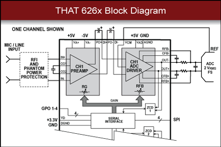
I do wonder how companies like THAT can produce their chips relatively affordably on tiny (~100 mm) wafers
Avatar
Avatar
Christopher
I do wonder how companies like THAT can produce their chips relatively affordably on tiny (~100 mm) wafers
What kinda chips?
Avatar
Audio
9:31 p.m.
Same with Sound Semiconductor, but I believe they're fabless
Avatar
Ahhh hmmm
Avatar
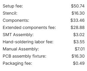
regarding pricing, I just ordered some PCB + assembly to test my chip a little easier than breadboard. Relatively simple 4 layer board (micro, headers, few level shifters, caps, resistors, only expensive part was a PSRAM module), moderate size.
  • $17.90 for 5pc
  • $159.75 for assembly
  • $46.47 for shipping
  • $78.84 for tariffs and taxes
all up that's $60 per board, plus $8.5 for the chip and COB. At qty 1000 and a better PCB that price could be brought down. But to hit $20 price point for PCB + chip COB, you'd probably have to assemble your own and keep the board ultra simple
(edited)
Avatar
Ehhhh, look at parallax propeller 2 for example, that's 130nm on semi "fabless" and fairly big (iirc the die could fit about 1.2~1.5 MiB SRAM from it's area; they only have 512 kiB shared plus 8 cores @4 kiB local each, but it's extremely powerful IO wise. E.g. each core could drive individual 180~250 MHz pixel clock VGA (256 pallet or fixed LUT optional, but it could sustain true color just no framebuffer to match). Each GPIO (64 of them) has 3 8-bit DACs, one 3ns VGA-class, ~123 Ohm, one ~600 Ohm, and one iirc ~15 kOhm (that one is used for the level comparator and some select related feedback modes of the pad "drivers"). It literally lets you set (sadly only 4 bit resolution) a "high" and a "low" code for the fast DAC to use for digital GPIO output state emission, so you can directly handle e.g. 1.2V CMOS levels, together with the input comparator.
Avatar
Avatar
BreakingTaps
regarding pricing, I just ordered some PCB + assembly to test my chip a little easier than breadboard. Relatively simple 4 layer board (micro, headers, few level shifters, caps, resistors, only expensive part was a PSRAM module), moderate size.
  • $17.90 for 5pc
  • $159.75 for assembly
  • $46.47 for shipping
  • $78.84 for tariffs and taxes
all up that's $60 per board, plus $8.5 for the chip and COB. At qty 1000 and a better PCB that price could be brought down. But to hit $20 price point for PCB + chip COB, you'd probably have to assemble your own and keep the board ultra simple
(edited)
Where in that breakdown are the "misc" components? The *assembly cost"?
9:48 p.m.
Propeller 2 is 12$ in quantity
9:49 p.m.
(last I looked)
9:50 p.m.
It's by far the fanciest "GPIO pad" of any microcontroller. (edited)
Avatar
Avatar
namibj
Where in that breakdown are the "misc" components? The *assembly cost"?
yeah lumped into assembly cost. Lemme find the BOM vs actual assembly breakdown
Avatar
Avatar
BreakingTaps
yeah lumped into assembly cost. Lemme find the BOM vs actual assembly breakdown
Just checking otherwise I'd have called out your choice of expensive assembly.
9:53 p.m.
I should sleep now.
Avatar
some of this would fall under NRE that amortizes over a lot of parts for sure, just expensive at such low quantity.
9:56 p.m.
but yeah, cost is mostly not the physical PCB or components. all in assembly, fixturing, setup fees, non-standard parts being loaded etc
Avatar
Fancy board to need fixture
Avatar
🤷‍♂️ I'm a PCB newbie and just yolo'd it, but it is double sided so that's probably why
💯 1
Avatar
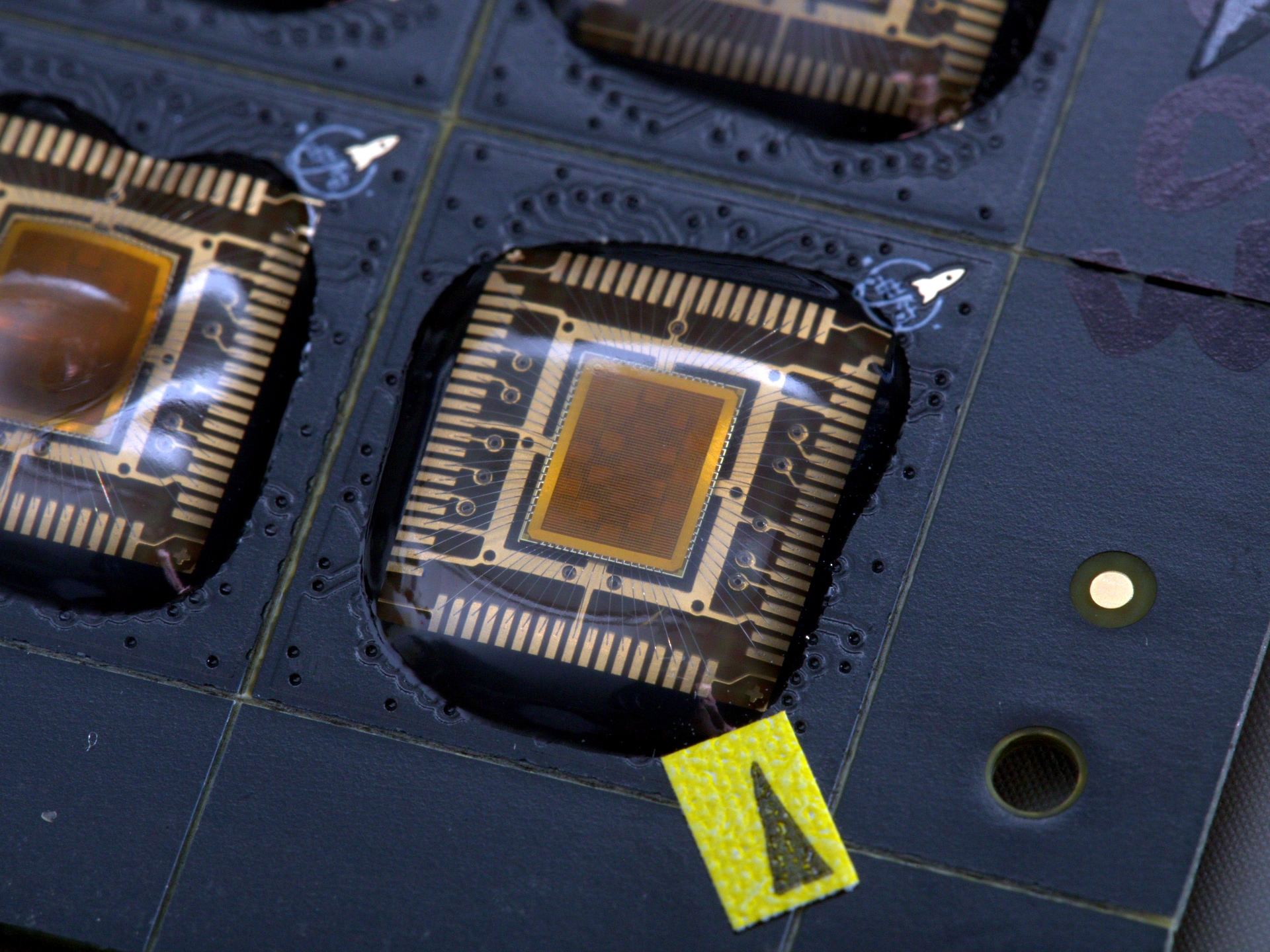
My serv based chip from run 1 is toggling GPIOs. With the help of a sacrificial iCEBreaker board (FTDI + QSPI + 12MHz oscillator already populated and connected) 🎉
🎉 8
🥳 4
3:24 a.m.
3:24 a.m.
Avatar
Avatar
Greg
My serv based chip from run 1 is toggling GPIOs. With the help of a sacrificial iCEBreaker board (FTDI + QSPI + 12MHz oscillator already populated and connected) 🎉
what that chip (good) for?
Avatar
An experiment with the serv + spram wrapper. It's an array of 23 seperate cores, plus some basic peripherals. A SPI loader on boot pre-loads each cores memory. (the above trace)
Avatar
Avatar
Greg
An experiment with the serv + spram wrapper. It's an array of 23 seperate cores, plus some basic peripherals. A SPI loader on boot pre-loads each cores memory. (the above trace)
Sorry, "serv" is too generic a term to make me confident to Google it and get the right thing. Got a link perhaps or such?
Avatar
SERV - The SErial RISC-V CPU. Contribute to olofk/serv development by creating an account on GitHub.
Avatar
Ahh sorry. Yes, not very googlable. "SErial Risc V" CPU.
Avatar
Are the commands for manually running klayout DRC and antenna rule check on a GDSII file documented anywhere?
Leo Moser (mole99) started a thread. 2026-06-09 4:31 p.m.
Avatar
Avatar
Leo Moser (mole99)
As for why it is the way it currently is, you would have to ask Mabrains as they created the original rule deck :) What I found in the docs:
3.4 Consistent layout all designs on a 0.005μm grid will avoid off-grid and snapping issues during database fracturing.
The design grid must be an integer multiple of 0.005μm.
Given the wording of the second statement, and that DRC errors in the design can lead to a back and forth with GF, it is probably safer and simpler to assume that all shapes on all layers need to be on the 5nm grid. As for the angle checks, I would actually love to be able to draw arbitrary angles (except for acute and as long as all points are on-grid). However, given the wording in the docs I'm not sure about this.
SH.2: Avoid any COMP, poly and metal shapes with acute angles (angles <90 deg). Exceptions are only for pre-tested metal inductors with IND_MK mark layers and lettering (non circuit elements).
This would tell me that arbitrary angles (except acute) are allowed on these layers. However this is contradicted by: https://gf180mcu-pdk.readthedocs.io/en/latest/physical_verification/design_manual/drm_03.html
3.6 Only 90 deg and 45 deg bends are allowed for poly and metal lines.
I wouldn't even dare to guess what this means for other layers 🤷‍♂️
"pre-tested metal inductors"? Do we have any? SH.1 says circular inductors are theoretically supported?
Avatar
Avatar
namibj
"pre-tested metal inductors"? Do we have any? SH.1 says circular inductors are theoretically supported?
Leo Moser (mole99) 2026-06-09 4:43 p.m.
As far as I know, no. However, we might see some inductors with 45-degree angles taped out on ws-run #2.
Avatar
Avatar
Leo Moser (mole99)
As far as I know, no. However, we might see some inductors with 45-degree angles taped out on ws-run #2.
If I can cook some suitable ones in the next few hours I expect to use some simple and some T-coil ones in the serializer. Would be nice to have those much sharper clock edges at the final MUX.
Avatar
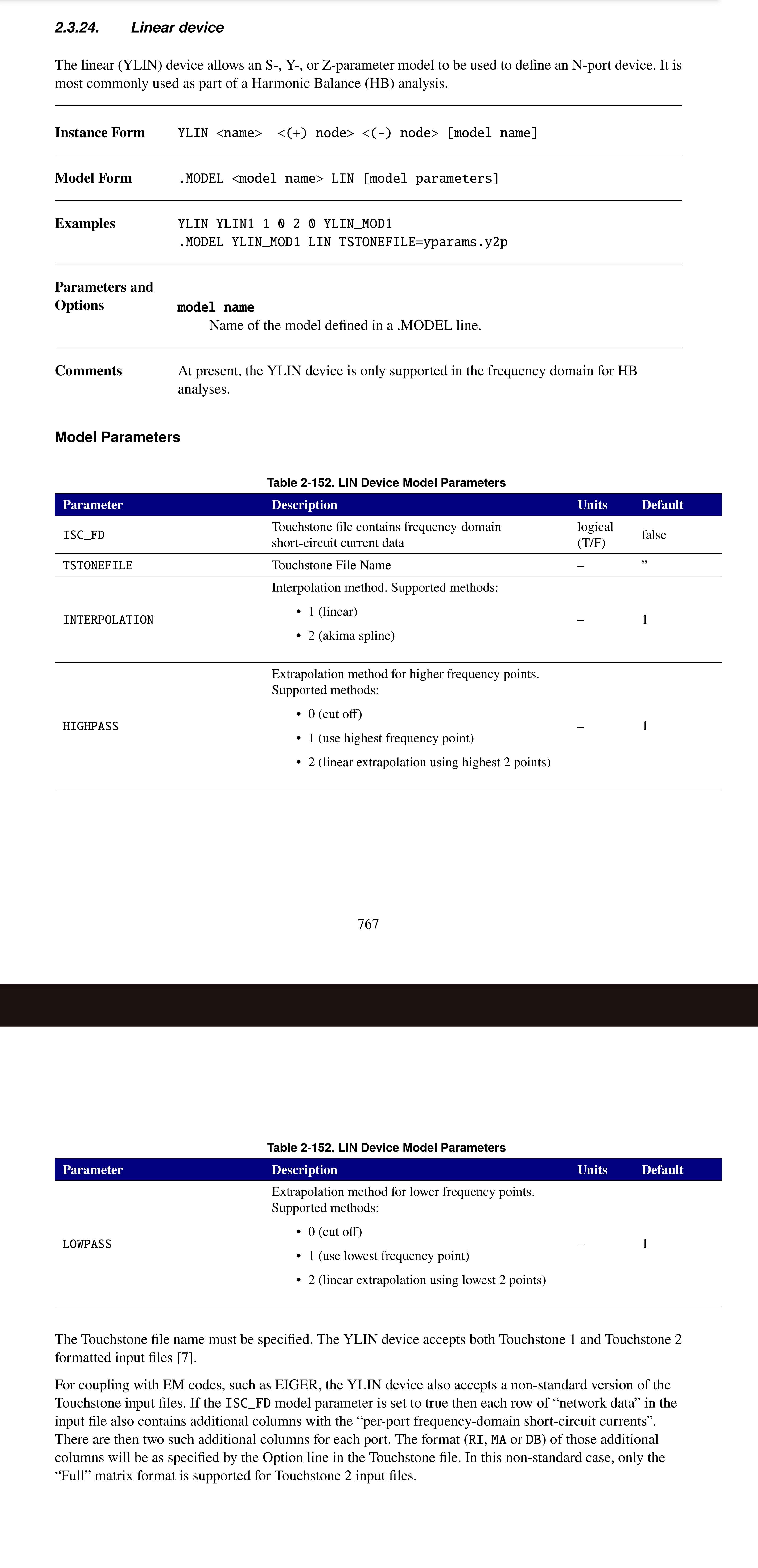
This seems like it might easily enough be adapted to our (gf18mcuD instead of that file's SG13G2) layer stack and would unlock generic "linear network" PEX one could hook up to SPICE (Xyce's easy way seems locked to harmonic balance aka large-signal (non-linear, with harmonics and intermodulation!) AC, but it shouldn't be too hard to make an analog behavioral model out of it (README.md "The resulting S-parameters can be used for simulation, but you can also extract a narrowband lumped element pi model using the pi-from-s2p tool.")) workflow/run_generic_nport.py:
# Model comments # # This is a generic model running port excitation for all ports defined below, # to get full [S] matrix data. # Output is stored to Touchstone S-parameter file. # No data plots are created by this script.

Avatar
Leo Moser (mole99) 2026-06-10 11:18 a.m.
@Ghaith Al Sabagh has already ported the XML to gf180mcuD for the IEEE Chipathon. He will tape out some inductors on ws-run #2.
Avatar
Ghaith Al Sabagh 2026-06-10 2:14 p.m.
Hi @namibj You would find the needed xml files for openEMS and palace AWS here: https://github.com/EngGhaith/The-Silent-Owl-GF180MCU-WB-LNA/tree/main/EM-Flow
The Silent Owl is an open-source LNA designed in GF180MCU for Chipathon 2026 - EngGhaith/The-Silent-Owl-GF180MCU-WB-LNA
Avatar
Avatar
Ghaith Al Sabagh
Hi @namibj You would find the needed xml files for openEMS and palace AWS here: https://github.com/EngGhaith/The-Silent-Owl-GF180MCU-WB-LNA/tree/main/EM-Flow
Ohh great! Are there any inductors already designed for that 2.4 GHz target I could maybe use as stand-in reference for my 2.5 GHz (design target, looks possible with (either) minor peaking into the final 4:1 MUX or (alternatively) employing 3-tap FIR between the mux node and the limiting amplifier acting as pre-driver for a current-mode adjustable-current (FIR tap) output driver (the tap's "PA")) clock tree buffers? Before specializing any further on serializer architecture and speed; I'd like to have physically feasible clock signal reference waveforms for designing (2:1 and the final 4:1) MUX cells, latch cells, and then doing a bit of floorplan "preliminary PnR" to know that overall design can fit into the ttgf0p3 tile I got.
Avatar
https://ieeexplore.ieee.org/document/11092168 ahh, yes, paywalls but it does sound like it has already scripted the port interfacing stuffs between OpenEMS and Xyce there, and it kinda sounds like they're bypassing the native Xyce limitation of it's YLIN device.
Avatar
Hmm I synthesized our design with AS 3v3 SCL, and it synthesized a dfxtp_4 cell but it isn't in the Verilog models
Avatar
the _4 is just drive strength though?
Avatar
Avatar
Jason Yang
Hmm I synthesized our design with AS 3v3 SCL, and it synthesized a dfxtp_4 cell but it isn't in the Verilog models
Leo Moser (mole99) 2026-06-11 7:29 a.m.
You can open an issue or pull request in this repository: https://github.com/AvalonSemiconductors/gf180mcu_as_sc_mcu7t3v3
Avatar
Avatar
Leo Moser (mole99)
You can open an issue or pull request in this repository: https://github.com/AvalonSemiconductors/gf180mcu_as_sc_mcu7t3v3
opened up an issue 👍
Avatar
Avatar
namibj
the _4 is just drive strength though?
I believe you have to duplicate the Verilog cell model for each drive strength as well
Avatar
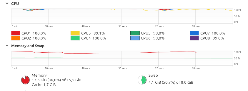
The new KLayout DRC setup is not messing around, I see
🚀 1
Avatar
Needs more ram consumption
Avatar
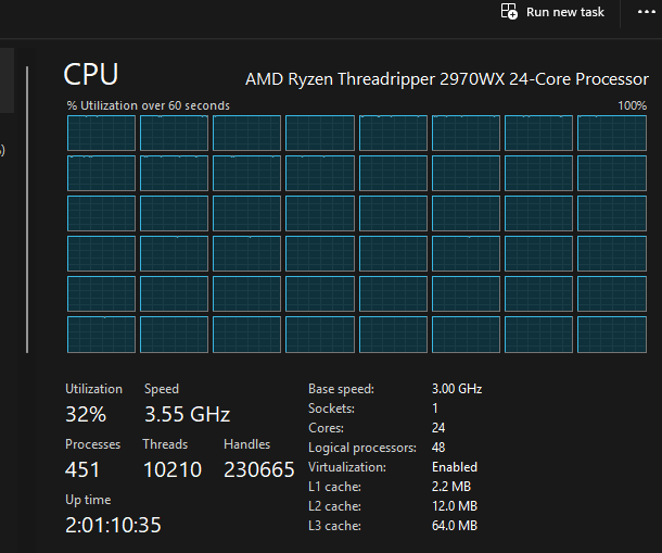
I found it worthwhile to run proper DRC jobs by spinning up an AWS r6i.2xlarge instance (8 vCPU, 64 GiB memory) -- it's $0.5 / hr in us-east-1 on demand, and my (fairly complex, analog) design generally takes <30 minutes. It's all scripted to spin up, copy over the changes to test, execute, wait to retrieve logs, and turn off. I kept hitting OOM issues on my (18GiB) laptop, 40 minutes in, so these sanity checks are worth the quarter per validation for me.
👍 3
Avatar
Avatar
dmv
I found it worthwhile to run proper DRC jobs by spinning up an AWS r6i.2xlarge instance (8 vCPU, 64 GiB memory) -- it's $0.5 / hr in us-east-1 on demand, and my (fairly complex, analog) design generally takes <30 minutes. It's all scripted to spin up, copy over the changes to test, execute, wait to retrieve logs, and turn off. I kept hitting OOM issues on my (18GiB) laptop, 40 minutes in, so these sanity checks are worth the quarter per validation for me.
yeah I'm so lucky I got plenty spare ram in my workstation
👍 1
Avatar
Kind of unrelated to wafer.space, but I can't seem to open Magic with OpenGL as the display driver.
7:42 p.m.
I'm using Magic bundled with the current flake in the project template
7:43 p.m.
Cairo and X11 works fine
Avatar
Which channel do I use for GDS submission bugs and issues?
Avatar
Avatar
J-Lo
Which channel do I use for GDS submission bugs and issues?
Leo Moser (mole99) 2026-06-16 5:11 p.m.
It seems Nikola has asked the question in https://discord.com/channels/1361349522684510449/1443758028393414818/1516487268443881512 We don't have a channel for the platform/precheck yet, so you can just ask in #⁉️-questions.
Avatar
Avatar
Jason Yang
Kind of unrelated to wafer.space, but I can't seem to open Magic with OpenGL as the display driver.
Leo Moser (mole99) 2026-06-16 5:11 p.m.
Can you please open an issue in: https://github.com/fossi-foundation/nix-eda
Nix flake for more up-to-date versions of EDA tools - fossi-foundation/nix-eda
❤️ 1
Avatar
18 hours!
🤯 2
Avatar
Wingate wants to take the wafer home it is done.
Avatar
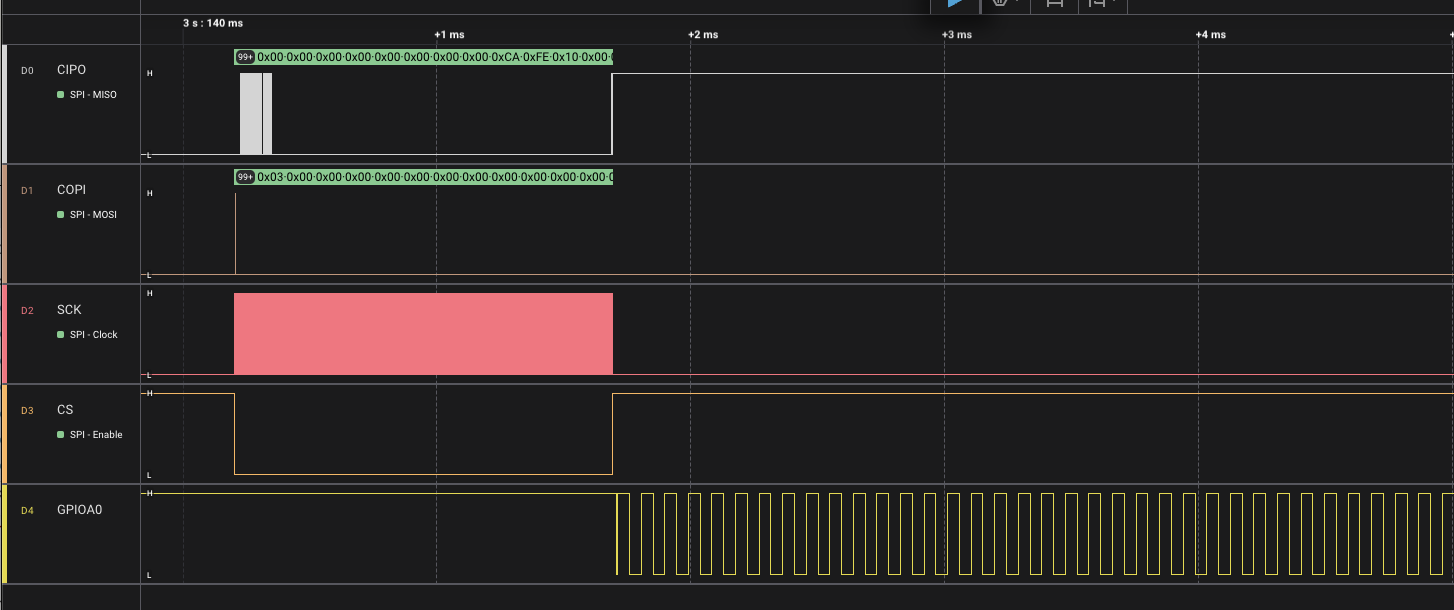
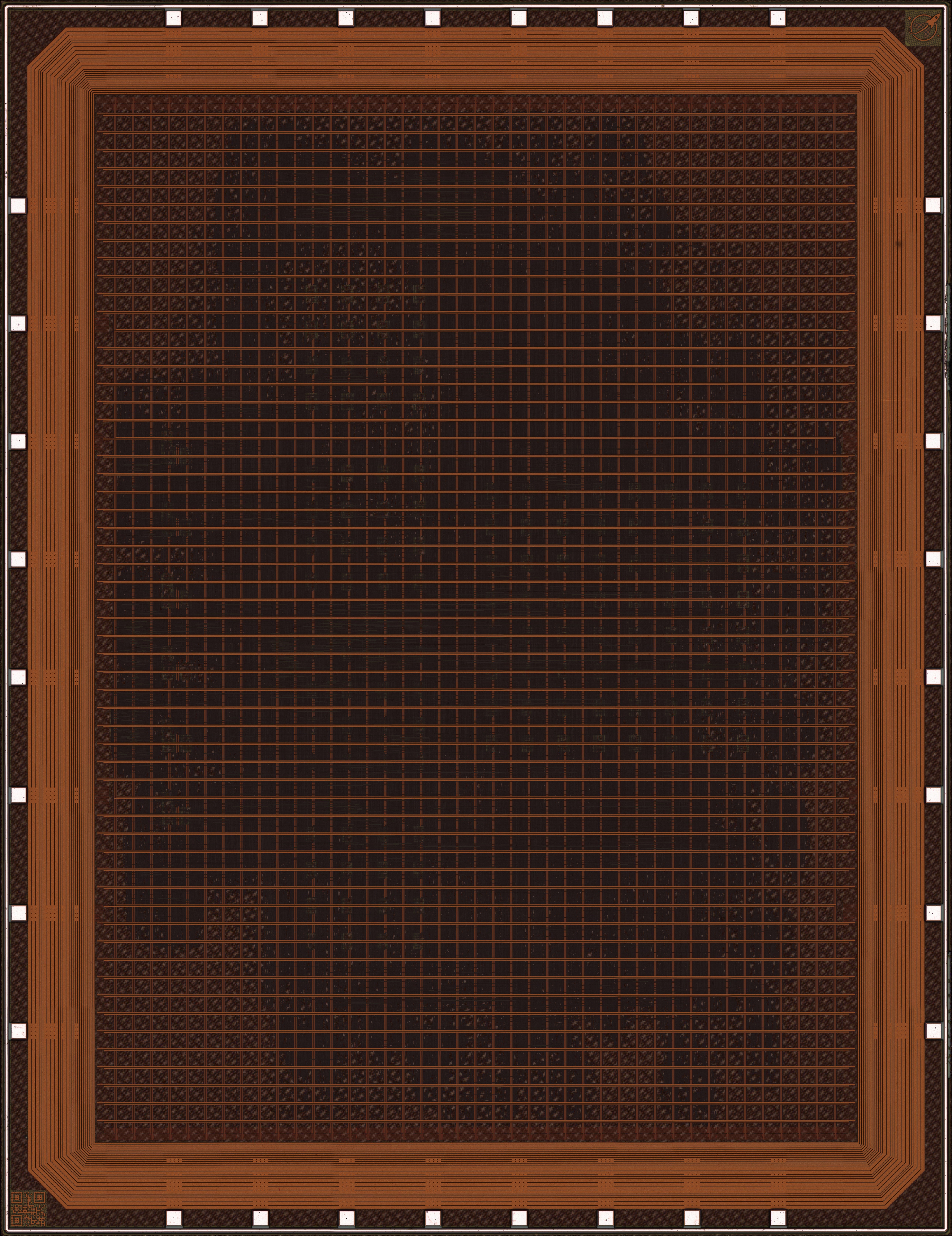
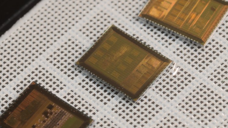
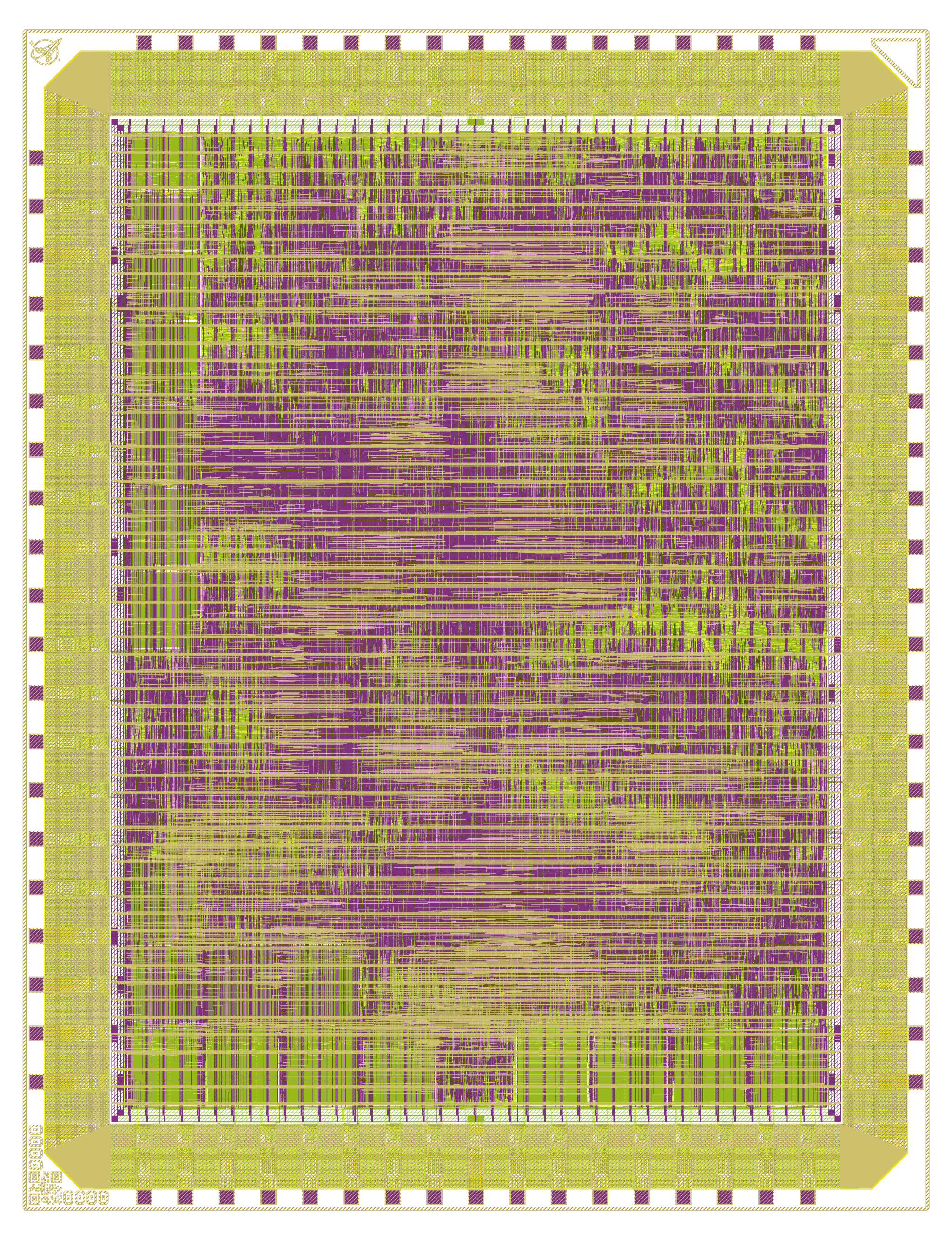
For anyone interested: Here's a frontside microscope image of my full die, best quality I could fit in Discord's 10 MB limit.
💜 2
12:20 p.m.
I will be able to share full SEM images of all (or most) layers in a few weeks/months. The picture above is optical microscopy obviously. (edited)
🙌 1
Avatar
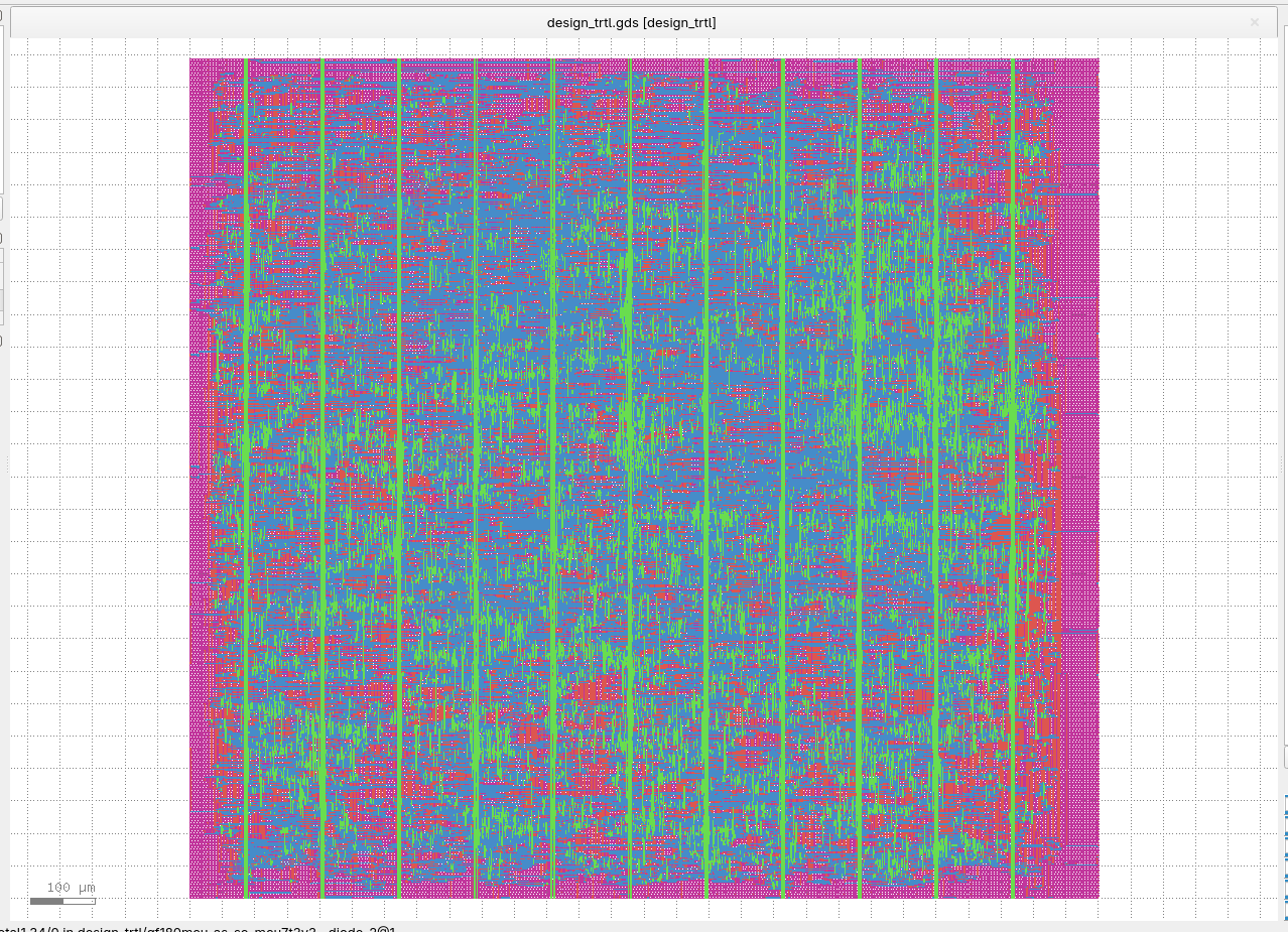
just might make run2 after all! The chip is a path tracer: two-way barrel processor (sorta), 8KB SRAM dedicated to hot tier of geometry, 768B SRAM for materials, HyperBus controller to talk to 8MB off-chip PSRAM. If it works, the plan is to array a bunch of these on a PCB and make a vaguely performant GPU First image is the result of 8hr iverilog simulation running through the full chip design, second image is a proxy render in python of what it should look like 🙂 Leaned on AI a lot for this one, so not super stoked about code quality. Think it'll probably end up as a "let's re-design this from scratch" sort of video series if/when I make one. Did learn a bunch about pipelining and debugging big combinatorial cones though!

👍 1
Avatar
I’ve been thinking of submitting a GPU to a future shuttle, but a rasterizer. Basically an array of RISC-y stream processors with some GPU bits around it. Like, the triangle queue or texture interpolators.
5:31 p.m.
But I’d like it to be self-contained on a single chip with maybe the option to do scan line interleaving with multiple independent GPUs
5:31 p.m.
I’ll give it a 32-bit address bus that’s fully broken out so I can give it up to 4GiB of memory and render anything I want given enough time
Avatar
that would be very cool! one thing I definitely under-appreciated is just how memory-bound path tracing ends up being. spend most of your time just waiting for PSRAM to return 😩 Would definitely design things differently next time around.

Avatar
I so hope I can get at least a PRBS C2 serializer filed before the deadline; C4 would of course be awesome. If the latter does succeed (in the short time left), and I manage to do so without breaking implementation bugs, we'd at least probably get to see shortly before Run3 whether we have a proper fast serial TX as suitable for (notably) digital GPU output. I'd be confident about it being fast enough for usual digital video PHYs; the wishful hope for the C4 is to maybe serialize fast enough to keep a 10GBASE-KR receiver listening if only I'd use the correct LFSR scambler and do some minimum valid framing structure. Not gonna happen for this deadline, though!
Avatar
Hello! I am an agentic engineer specializing in software development across various fields, including AI, full-stack, mobile app development, and e-commerce (Include of Web3 & dApp). Until two years ago, I worked on coding line by line, but recently, I have been handling all tasks directly using coding agents. In the past year alone, I have participated as a Lead Engineer in several projects and have devoted significant effort to architecture design. No matter how complex the logic, the development process runs smoothly as long as the architecture is well-designed. I enjoy finding correct way in crowded environments and solving complex problems simply. If you have a promising project, please contact me.
Avatar
Tim 'mithro' Ansell 2026-06-18 4:26 a.m.
Avatar
Avatar
Tim 'mithro' Ansell
Click to see original message
Egor Lukyanchenko 2026-06-18 4:28 a.m.
Options 2 and 3 should be 14 July / 30 July, not June. (edited)
Avatar
Avatar
Thorben
For anyone interested: Here's a frontside microscope image of my full die, best quality I could fit in Discord's 10 MB limit.
Tim 'mithro' Ansell 2026-06-18 4:31 a.m.
Could you upload to @digshadow's SiliconPrawn site?
👍 1
Avatar
Avatar
Egor Lukyanchenko
Options 2 and 3 should be 14 July / 30 July, not June. (edited)
Tim 'mithro' Ansell 2026-06-18 4:34 a.m.
Dammit! I recreated the poll with the correct dates.
👍 1
Avatar
Egor Lukyanchenko 2026-06-18 5:02 a.m.
I would like to advocate for a 1-month extension here if it’s Ok. A lot of people are using 3.3V OCD SRAMs in their Run 2 designs, and as discussed in the #📝-project-template channel, the earliest @Tim Edwards will be able to begin testing those is a week or so from now. I guess if everything goes according to plan, we're likely to get some conclusive data sometime around the original deadline. This means that if there is any major problem, people won’t have enough time to change their designs and might end up with non-functional chips. And I’m not even talking about the AS 3.3V SCL… 😅 Also there were some significant updates to the project template just recently and a transition to the openpdks PDK repos, and it takes time to accommodate and verify those.
👍 2
Avatar
Seems like there was a significant jump in slots bought recently? The Crowdsupply page now lists 16 full size slots, I think last time I checked it was 6 or 7?
🚀 1
Avatar
Avatar
Oliver
Seems like there was a significant jump in slots bought recently? The Crowdsupply page now lists 16 full size slots, I think last time I checked it was 6 or 7?
I just bought one. I needed to get my design to complete before I was confident enough to purchase. Having missed the early bird, it didn't make sense to buy before I knew my scheme could fit. I imagine I'm not alone in that behavior, and that this will be a common pattern between runs.
Avatar
Avatar
Jason Yang
Kind of unrelated to wafer.space, but I can't seem to open Magic with OpenGL as the display driver.
Didn't see this message until today; you can message me directly with questions about magic.
Avatar
Avatar
Tim Edwards
Didn't see this message until today; you can message me directly with questions about magic.
Leo Moser (mole99) 2026-06-18 1:30 p.m.
In this case, however, I assume the issue is with the Nix derivation and not magic itself.
Avatar
Tim 'mithro' Ansell 2026-06-19 12:08 a.m.
Avatar
Andrew Wingate 2026-06-19 2:24 a.m.
Read the article on @asic destroyer die from Run #1 Looking forward to see this boot!! https://www.crowdsupply.com/wafer-space/gf180mcu-run-2/updates/taping-out-kianv-a-linux-xv6-capable-risc-v-soc
In this update we'll be exploring a homegrown SoC which is capable of booting Linux, µLinux and XV6. It implements the RISC-V RV32IMA ISA alongside additional extensions for more functionality.
❤️ 1
Avatar
I don’t think this description of Run 1 is accurate anymore, @Tim 'mithro' Ansell :P
Avatar
Also, I promise I’ve been working on a Run 2 submission using only my 3.3 SCL for the full chip, but I’m just not yet ready to show anything
9:43 a.m.
I can only say: there will be more art
😍 3
Avatar
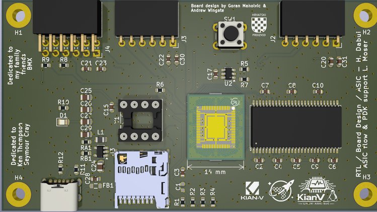
how many pins are there? the COB connector has something like 84?
Avatar
Avatar
carlfk
how many pins are there? the COB connector has something like 84?
Andrew Wingate 2026-06-19 9:29 p.m.
70
Avatar
Of which 56 are for signals, the rest are power
💜 1
Avatar
Andrew Wingate 2026-06-20 8:17 a.m.
Hey TinyTapeout team, I'm trying to get a bit of a tutorial thing going and was looking for what you guys and was looking for guides. I see sywater and IHP, is there no GF? Does that matter? https://tinytapeout.com/hdl/templates/ Thanks!
Handy templates to help submit faster with an HDL
Avatar
Avatar
Tholin
The new KLayout DRC setup is not messing around, I see
I noticed the same thing
Avatar
That must finish fast for you, though
12:06 p.m.
I still wanna know how I can enable this multithreading when hardening my macros
Avatar
That's above my pay grade.
Avatar
Avatar
Tholin
I still wanna know how I can enable this multithreading when hardening my macros
Leo Moser (mole99) 2026-06-20 12:53 p.m.
Avatar
Thanks. That’s gonna make things go by so much faster for me.
👌 1
Avatar
oh, also, on the matter of test structures requested for the e-test things on Run2: 1. MOS structures with bent gates (PDK says the DRC allow 45 degree bends of gate poly (on active!), but I'm pretty sure that's not in any real way tested for extraction/SPICE). 2. MOS structues with multiple fingers in series without contacts on the intermediate, such as those that happen in NAND gates in NMOS logic (and are part of the AOI/OAI gate family in CMOS).
Avatar
Avatar
Tholin
Thanks. That’s gonna make things go by so much faster for me.
Andrew Wingate 2026-06-21 5:02 a.m.
So @Tholin those runs ended up failing on me. More generally I'm trying to get a starter kit that is easy for people to start with and creates some docker containers with a sample project. Seems there is an issue with the version of KLayout that comes with the LibreLane container. I have run it a few times and was only able to finish when I set workers to 1 Seems it's an issue with the KLayout version that ships with the container and should be updated to a newer version. @Leo Moser (mole99) or others, would you like for me to create an issue on github? I can share more details if needed. Thanks (edited)
Beginner-friendly, Docker-based starter kit for designing a GF180MCU chip from RTL to a manufacturable GDSII — simulate, verify, and harden a working example, then make it yours and submit it to a ...
Avatar
Avatar
Andrew Wingate
So @Tholin those runs ended up failing on me. More generally I'm trying to get a starter kit that is easy for people to start with and creates some docker containers with a sample project. Seems there is an issue with the version of KLayout that comes with the LibreLane container. I have run it a few times and was only able to finish when I set workers to 1 Seems it's an issue with the KLayout version that ships with the container and should be updated to a newer version. @Leo Moser (mole99) or others, would you like for me to create an issue on github? I can share more details if needed. Thanks (edited)
Leo Moser (mole99) 2026-06-21 10:02 a.m.
You need at least KLayout 0.30.9 for the new DRC runner. That's why the project template uses Librelane dev.
Avatar
Avatar
Leo Moser (mole99)
You need at least KLayout 0.30.9 for the new DRC runner. That's why the project template uses Librelane dev.
Yeah, I guess I'm referring to the latest containerized version ghcr.io/librelane/librelane:3.1.0.dev1 which comes with KLayout 0.30.7
Avatar
Avatar
Andrew Wingate
Yeah, I guess I'm referring to the latest containerized version ghcr.io/librelane/librelane:3.1.0.dev1 which comes with KLayout 0.30.7
Leo Moser (mole99) 2026-06-21 10:11 a.m.
I see! Yes, the docker container is only ever built on a version increase and dev hasn't seen one for quite a while. I'll make sure to bump the version.
Avatar
Avatar
Leo Moser (mole99)
I see! Yes, the docker container is only ever built on a version increase and dev hasn't seen one for quite a while. I'll make sure to bump the version.
Thanks 💜
Avatar
Egor Lukyanchenko 2026-06-21 3:44 p.m.
I'm happy to report that my eFuse IPs taped out on the Run 1 testchip seem to be working fine. For now only one chip was tested, but all Wishbone and async eFuse blocks (a total of around 35kBits) were written and read correctly as long as enough current was supplied during write (around 15mA at 5V per "burning" bit). Write works reliably only with 5V supply, but if burned at 5V, read worked fine at least down to 3.3V. Also the short read endurance test was performed, and 160 tested efuse bits (around half of them in "burned" state) survived 200 million reads without failures. For conclusive results more chips have to be tested, but these first tests look promising for future use of eFuses in 5V designs.
🎉 11
🔥 1
Avatar
Avatar
Andrew Wingate
Thanks 💜
Leo Moser (mole99) 2026-06-21 6:12 p.m.
LibreLane Docker image ghcr.io/librelane/librelane:3.1.0.dev2 is now available.
💜 1
Avatar
Avatar
Egor Lukyanchenko
I'm happy to report that my eFuse IPs taped out on the Run 1 testchip seem to be working fine. For now only one chip was tested, but all Wishbone and async eFuse blocks (a total of around 35kBits) were written and read correctly as long as enough current was supplied during write (around 15mA at 5V per "burning" bit). Write works reliably only with 5V supply, but if burned at 5V, read worked fine at least down to 3.3V. Also the short read endurance test was performed, and 160 tested efuse bits (around half of them in "burned" state) survived 200 million reads without failures. For conclusive results more chips have to be tested, but these first tests look promising for future use of eFuses in 5V designs.
Can you tease us with density information that one would get from that memory technology?
Avatar
Avatar
Egor Lukyanchenko
I'm happy to report that my eFuse IPs taped out on the Run 1 testchip seem to be working fine. For now only one chip was tested, but all Wishbone and async eFuse blocks (a total of around 35kBits) were written and read correctly as long as enough current was supplied during write (around 15mA at 5V per "burning" bit). Write works reliably only with 5V supply, but if burned at 5V, read worked fine at least down to 3.3V. Also the short read endurance test was performed, and 160 tested efuse bits (around half of them in "burned" state) survived 200 million reads without failures. For conclusive results more chips have to be tested, but these first tests look promising for future use of eFuses in 5V designs.
How do you extract the efuses? Is there already a model in the PDK/rule decks?
Avatar
Avatar
Egor Lukyanchenko
I'm happy to report that my eFuse IPs taped out on the Run 1 testchip seem to be working fine. For now only one chip was tested, but all Wishbone and async eFuse blocks (a total of around 35kBits) were written and read correctly as long as enough current was supplied during write (around 15mA at 5V per "burning" bit). Write works reliably only with 5V supply, but if burned at 5V, read worked fine at least down to 3.3V. Also the short read endurance test was performed, and 160 tested efuse bits (around half of them in "burned" state) survived 200 million reads without failures. For conclusive results more chips have to be tested, but these first tests look promising for future use of eFuses in 5V designs.
Woohoo, finally some on-die non-volatile memory on an open-source PDK! Sure it's one-time programmable, so just... don't make mistakes 😝. Really awesome though, could be very nice for provisioning per-chip keys or permanently enabling/disabling configs or features. Great work, I'll be using it!
👍 1
Avatar
This error has been haunting me the entire time I’ve been developing this chip
Avatar
Avatar
kcolley
Woohoo, finally some on-die non-volatile memory on an open-source PDK! Sure it's one-time programmable, so just... don't make mistakes 😝. Really awesome though, could be very nice for provisioning per-chip keys or permanently enabling/disabling configs or features. Great work, I'll be using it!
enables OTP gate arrays which are super handy
👍 2
Avatar
@Egor Lukyanchenko So there are some links for folks to explore more. Are these correct? Compiler https://github.com/egorxe/gf180_efuse_compiler Precompiled blocks https://github.com/egorxe/gf180mcu_re_efuse run1 design: https://github.com/ZeduloTech/gf180mcu-testchip2025
Avatar
Avatar
Greg
@Egor Lukyanchenko So there are some links for folks to explore more. Are these correct? Compiler https://github.com/egorxe/gf180_efuse_compiler Precompiled blocks https://github.com/egorxe/gf180mcu_re_efuse run1 design: https://github.com/ZeduloTech/gf180mcu-testchip2025
Egor Lukyanchenko 2026-06-22 2:17 a.m.
Yes. Also, the precompiled blocks are now available with the open_pdks PDK installation.
Avatar
Avatar
bailey
How do you extract the efuses? Is there already a model in the PDK/rule decks?
Egor Lukyanchenko 2026-06-22 2:24 a.m.
Extraction models are available in both Magic and KLayout. Magic extracts efuse cell as a subcircuit and KLayout as a 100 Ohm resistor.
👍 1
Avatar
Avatar
namibj
Can you tease us with density information that one would get from that memory technology?
Egor Lukyanchenko 2026-06-22 2:27 a.m.
Raw eFuse array density (without digital wrappers) is ~10 kBit/mm^2. No teases here, you can check it yourself just by looking in the GDS 😄. (edited)
Avatar
Tim 'mithro' Ansell 2026-06-22 2:51 a.m.
So, https://platform.wafer.space seems like it is up and running. Can people give it a try?
Platform for wafer.space low cost silicon manufacturing.
👍 1
Avatar
Avatar
Leo Moser (mole99)
LibreLane Docker image ghcr.io/librelane/librelane:3.1.0.dev2 is now available.
Andrew Wingate 2026-06-22 8:39 a.m.
I updated all the images and everything worked to completion. Thanks!!
👍 1
Avatar
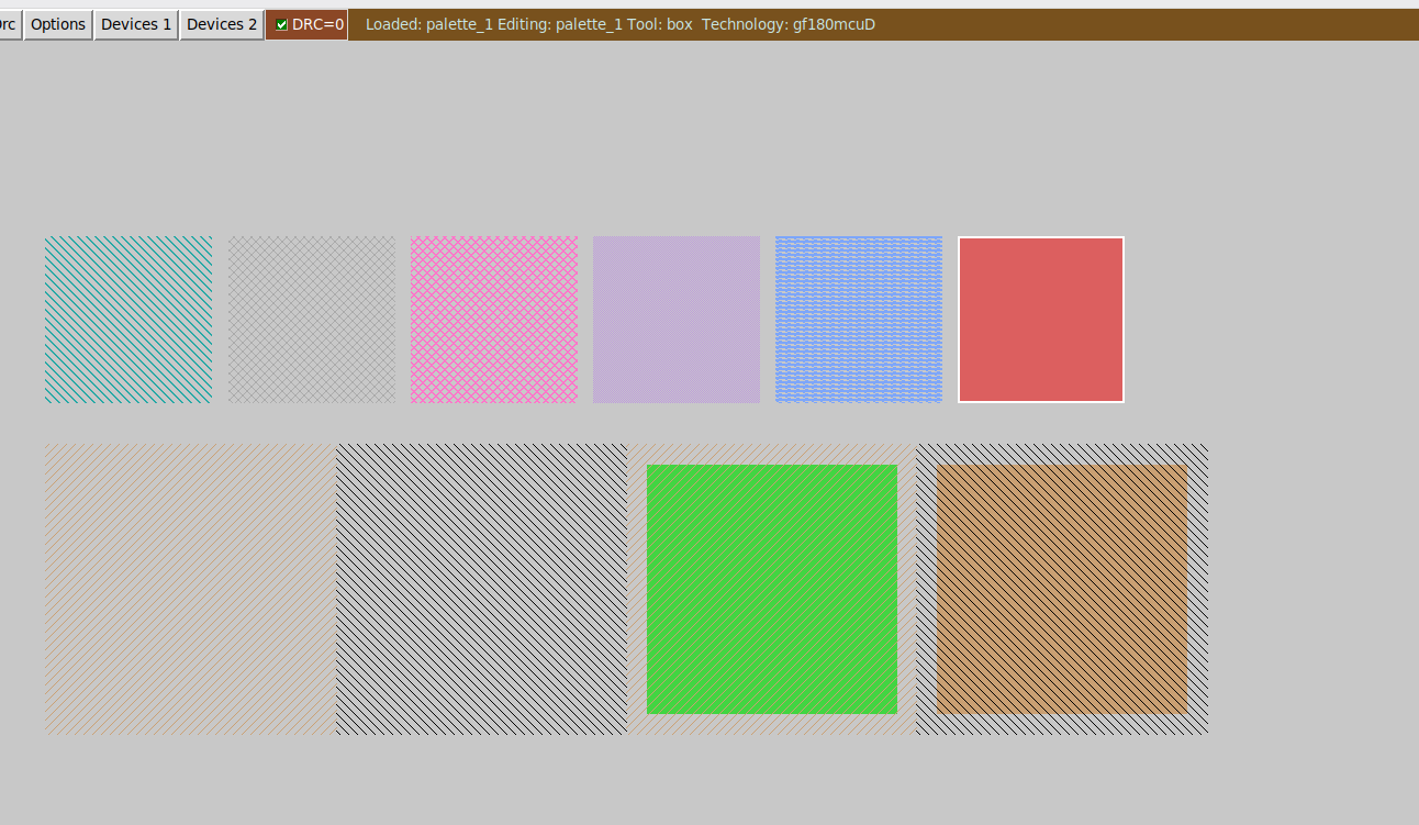
I am putting together a palette which I will tape out on this shuttle, to be imaged under a microscope and used to help future artistic efforts
👍 1
😍 1
Avatar
Does the lack of a delay announcement mean we’re sticking with June 30 tape out? @Tim 'mithro' Ansell
this 2
Avatar
Does anyone know any "good" use for the allowed 45 degree bends of poly2 on comp (i.e., bent gates)?: PL.7 says they only have to be mildly longer (gate length; poly2 "width") than minimums for straight gates: https://gf180mcu-pdk.readthedocs.io/en/latest/physical_verification/design_manual/drm_07_08.html
9:07 p.m.
Saving a bit of space on contacts ...
Avatar
Avatar
tnt
Saving a bit of space on contacts ...
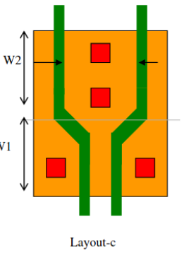
Do these techniques matter enough to care about designing with them (and thus looking at covering the extent that gate structure affects extraction/SPICE in the E-test)? I'd figure it might also come into play for escaping the gate fingers to a pitch they can be independently contacted, c.f. if the W2 section depicted doesn't have diffusion contacts, but is still needed for the gate poly to be contacted directly)?
Avatar
The DFM rules basically say to avoid these is you expect any kind of precision for your devices 😅
Avatar
Avatar
tnt
The DFM rules basically say to avoid these is you expect any kind of precision for your devices 😅
Hmmmpf. (Do they litho in poorly reproducible fashion, or what's going on there to explain them being only-usable-for-digital-switching?
Avatar
Avatar
J-Lo
Does the lack of a delay announcement mean we’re sticking with June 30 tape out? @Tim 'mithro' Ansell
also curious how stressed I need to be this week with trying to wrap up my design 🙂
💯 1
Avatar
Avatar
BreakingTaps
also curious how stressed I need to be this week with trying to wrap up my design 🙂
Tim 'mithro' Ansell 2026-06-23 7:07 a.m.
I was suppose to have a meeting with CrowdSupply this morning but they didn't turn up
👍 1
❤️ 1
Avatar
How many slots are used ATM ? I know TT takes 3 slots. Not sure if it's counted in the "17 people loves us" on crowdsupply.
7:14 a.m.
Interestingly CS seems to let me pick a half width slot, but AFAIK there are only 4 of those and they're already taken.
Avatar
Avatar
tnt
Interestingly CS seems to let me pick a half width slot, but AFAIK there are only 4 of those and they're already taken.
Leo Moser (mole99) 2026-06-23 7:23 a.m.
We added one more vertical and one more horizontal cut to this shuttle run. This means that there are fewer full slots, but more half slots in total.
Avatar
Oh I see. So only 18 full slots.
Avatar
Leo Moser (mole99) 2026-06-23 7:26 a.m.
That's right. We may still rearrange things based on the final allocation, but this is what we planned with.
👍 1
Avatar
Avatar
BreakingTaps
also curious how stressed I need to be this week with trying to wrap up my design 🙂
I'm sure everyone is looking for a definitive answer. As far as I understand, Tim has been talking with the people who do the final review of wafer.space completed reticle before it's actually sent to the fab. For some time, we have had a date on the calendar for when they should expect us to get that to them. That said; there are also those internally that are wanting the couple weeks. Again, sorry for the lack of information, there are many people this must go through and it's not just us. Thanks for being patient.
👍 1
❤️ 1
Avatar
One thing that worries me a bit if there is a delay is that the review result will be right at the beginning of my vacation and so so I wouldn't be able to fix anything for 2 weeks ...
Avatar
Perhaps the review in question can be applied per regular schedule for those who need it (like tnt)?
Avatar
@namibj Maybe I misunderstood from run1, but IIRC some of the review is done on the full reticle when submitting it so you need it all ready.
Avatar
Avatar
tnt
@namibj Maybe I misunderstood from run1, but IIRC some of the review is done on the full reticle when submitting it so you need it all ready.
Technically yeah, but the only DRC that way should be density rules and I'd assume that to be fairly straight-forward to account for? Like, it doesn't 100% rule out, but it should catch any actual issues that arise from the foundry using different DRC decks/engines than the open PDK.
Avatar
No I meant the test is run by the foundry and they won't bother with testing your designs one by one and will wait for your final submission before bothering. (edited)
Avatar
Leo Moser (mole99) 2026-06-23 12:57 p.m.
Yes, we receive feedback from GF after submitting the full reticle. Hopefully, no changes will be required on your end. However, if there is an issue that can't be easily fixed, we'll contact you.
Avatar
@Leo Moser (mole99) Yeah the question is when would that be with the current deadline and with any potential delayed deadline .. because that means we need to be somewhat available to make changes and update the design ...
Avatar
Avatar
tnt
@Leo Moser (mole99) Yeah the question is when would that be with the current deadline and with any potential delayed deadline .. because that means we need to be somewhat available to make changes and update the design ...
Leo Moser (mole99) 2026-06-23 1:10 p.m.
Unfortunately, I can't say for certain. We need to wait for Tim to announce the final deadline.
Avatar
cheers for the udpate @Andrew Wingate @Tim 'mithro' Ansell 🙂
💜 1
2:25 p.m.
i shall self-apply the sufficient stress assuming it's due on the original deadline 😄
Avatar
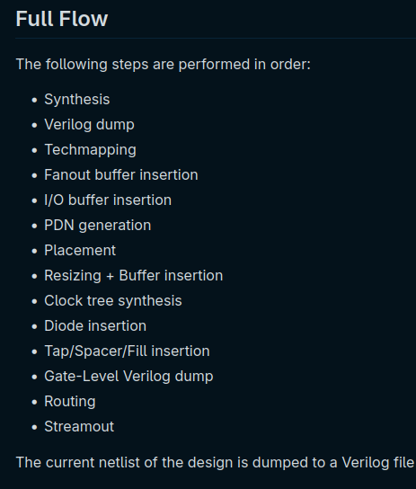
I may or may not have been cooking for a couple months here. Intending to set a record.
😮 1
❤️ 1
3:41 p.m.
Most intense 8000 lines of C code I’ve ever written
3:41 p.m.
This is why I’m late to the party getting my chip ready
Avatar
Is this the C version of @htamas MicroLane?
4:46 p.m.
I started from scratch
4:47 p.m.
I intentionally did NOT look at MicroLane's code
Avatar
No sorry, what I meant was it's trying the same thing, a complete RTL to GDS flow
5:06 p.m.
I'm interested in the compromises - did you do CTS?
Avatar
Yes, I did
😎 2
7:07 p.m.
Here is all the steps I implemented
👍 2
Avatar
Tim 'mithro' Ansell 2026-06-24 6:57 a.m.
🔥 2
❤️ 4
Avatar
Avatar
Tholin
Here is all the steps I implemented
Wow, incredible work!
Avatar
Leo Moser (mole99) 2026-06-24 7:22 a.m.
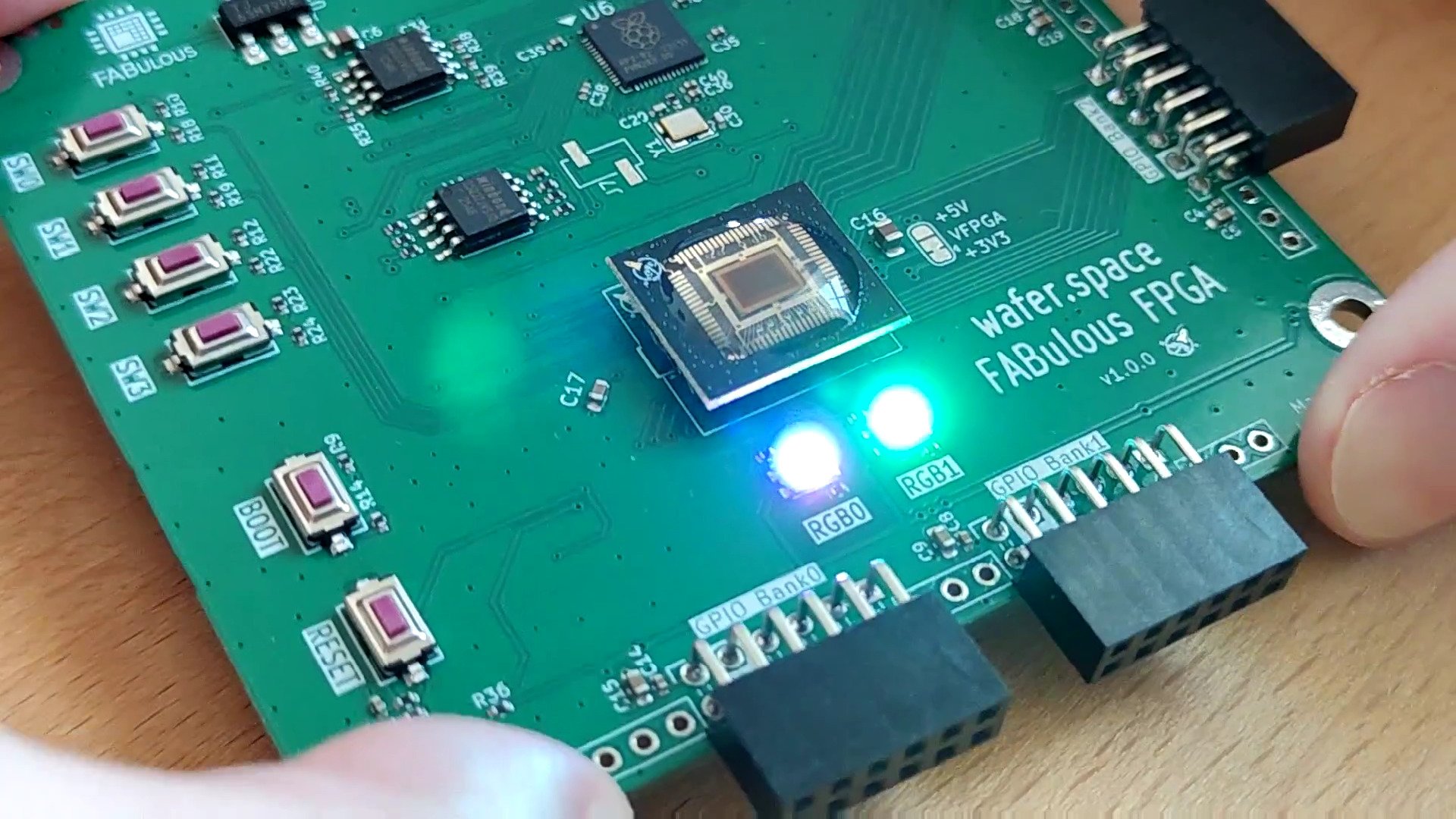
I have finally tested my FPGA from wafer.space Run 1, and I'm happy to say that it is functional! Video: https://makertube.net/w/fBWTsw5hSzG7AaeEb9tMCn
This chip is part of wafer.space Run 1 (https://github.com/wafer-space/ws-run1), which was taped out at the end of last year. It is built using the FABulous (e)FPGA framework and the wafer.space Li...
❤️ 7
🎉 10
waferspace 2
😆 1
Avatar
Avatar
Leo Moser (mole99)
I have finally tested my FPGA from wafer.space Run 1, and I'm happy to say that it is functional! Video: https://makertube.net/w/fBWTsw5hSzG7AaeEb9tMCn
Awesome work! Will people like me be able to get their hands on one or a few of these? Would be happy to pay for it, ideally for assembled and tested boards. For my branch of research, a fully open-silicon FPGA seems like an awesome tool.
7:41 a.m.
Second question, do you plan to tapeout bigger versions in the future? 🙂
Avatar
Avatar
Thorben
Awesome work! Will people like me be able to get their hands on one or a few of these? Would be happy to pay for it, ideally for assembled and tested boards. For my branch of research, a fully open-silicon FPGA seems like an awesome tool.
Leo Moser (mole99) 2026-06-24 7:50 a.m.
I currently have 20 chips at home that I still need to sort through. Of the four I have tested so far, all were good for the features I tested. First, I need to send some boards to people I have already promised them to. After that, I'll get in touch again. Please note, however, that this is still an experimental version. It uses the 5V transistors at 3.3V, which generally means a slower fabric. The second version that I'm working on has a better architecture with 4 GBUFs and uses the 3.3V IPs (we'll see if they work). I'm already using a full slot on wafer.space, so a bigger version will only be possible if we do laser dicing at some point 😉
👍 2
❤️ 1
Avatar
Does the t/o extension have any impact on when we'd expect the silicon back?
Avatar
Finally, I have something. Plenty of space for art, I think.
👍 1
❤️ 2
🎉 3
Avatar
Oh, given we have some extra time, i'm thinking of throwing something together to characterise @Tholin's 3.3v library - unless someone else is already doing this?
Avatar
I’m not
Avatar
What open tool do you prefer for compiling chisel to gdsii? (edited)
12:56 p.m.
I have tried librelane and SiliconCompiler
12:57 p.m.
I am trying to learn this space, but as a swe every tool really lacks in DX
12:59 p.m.
I don't know how people do it for "real" but I'm interested in building some reusable macros for complex stuff that will be repeated. Afaik this is a common technique.
1:01 p.m.
It would be so sweet if one could just declare this somehow and not needing to tweak so many config files everywhere.
Avatar
Avatar
Tholin
I may or may not have been cooking for a couple months here. Intending to set a record.
always_ff_rohan 2026-06-24 4:04 p.m.
this is not OSS yet?
Avatar
Avatar
Rob Taylor
Oh, given we have some extra time, i'm thinking of throwing something together to characterise @Tholin's 3.3v library - unless someone else is already doing this?
If there's anything in particular I'd be able to help with for that, do let me know.
Avatar
Avatar
Olle
I have tried librelane and SiliconCompiler
I'd probably stick with librelane since wafer.space provides a project template for it (and it's very good! pretty easy to drop your RTL in and hit compile)
👍 1
Avatar
Tim 'mithro' Ansell 2026-06-25 7:27 a.m.
@Rob Taylor - I think the GDSFactory team was interested in doing some general characterization stuff.
Avatar
Avatar
Rob Taylor
Oh, given we have some extra time, i'm thinking of throwing something together to characterise @Tholin's 3.3v library - unless someone else is already doing this?
Tim 'mithro' Ansell 2026-06-25 7:28 a.m.
@Thomas Pluck 2.1 - Where you going to include standard library stuff in any way?
Avatar
Avatar
Leo Moser (mole99)
I currently have 20 chips at home that I still need to sort through. Of the four I have tested so far, all were good for the features I tested. First, I need to send some boards to people I have already promised them to. After that, I'll get in touch again. Please note, however, that this is still an experimental version. It uses the 5V transistors at 3.3V, which generally means a slower fabric. The second version that I'm working on has a better architecture with 4 GBUFs and uses the 3.3V IPs (we'll see if they work). I'm already using a full slot on wafer.space, so a bigger version will only be possible if we do laser dicing at some point 😉
Tim 'mithro' Ansell 2026-06-25 7:29 a.m.
FYI - I think there is a bunch we can do to increase density of your FPGA
Avatar
Avatar
Tim 'mithro' Ansell
FYI - I think there is a bunch we can do to increase density of your FPGA
Leo Moser (mole99) 2026-06-25 7:33 a.m.
Oh, there definitely is :) First thing would be to design a custom passgate multiplexer with integrated SRAM cells. That should increase the density considerably, however, it also affects the speed.
💜 1
👍 1
Avatar
Avatar
Tim 'mithro' Ansell
@Rob Taylor - I think the GDSFactory team was interested in doing some general characterization stuff.
thanks Tim will check out
Avatar
The default KLayout layer properties file, that is also used for the renders, has HORRIBLE color contrast between the metal layers which makes it nearly unusable. I think this is better.
❤️ 1
👍 1
Avatar
I'd like to announce the first official release of Jacquard - a GPU accelerated, timing aware and gate-level capable simulator. Apple GPU, NVIDIA and AMD are supported (though AMD less tested due to lack of github runners) It currently has support for gate level simulation of SKY130 and GF180 standard cells, and the upcoming 0.3 will be able to support any cell library. I've been using it for my recent wafer.space designs 😁 Please dig in and report any issues!
Open-source RTL logic simulator with GPU acceleration (Metal, CUDA, HIP/AMD) - gpu-eda/Jacquard
👍 1
Avatar
Avatar
Rob Taylor
I'd like to announce the first official release of Jacquard - a GPU accelerated, timing aware and gate-level capable simulator. Apple GPU, NVIDIA and AMD are supported (though AMD less tested due to lack of github runners) It currently has support for gate level simulation of SKY130 and GF180 standard cells, and the upcoming 0.3 will be able to support any cell library. I've been using it for my recent wafer.space designs 😁 Please dig in and report any issues!
Will we eventually get latches?
Avatar
Avatar
namibj
Will we eventually get latches?
in what sense?
Avatar
Avatar
Rob Taylor
in what sense?
It says they're not supported.
Avatar
ah, async logic - maybe evetually, but thats a bugger to do fast with the scheme i use to accelerate on gpu
6:57 p.m.
will clairify that line
Avatar
Not necessarely async logic but it's not uncommon to use latch with clock gates for memory to save space.
Avatar
105 +- **Edge-triggered flip-flops only** — *latches* (level-sensitive storage) are 106 + not supported. Asynchronous **set/reset on flip-flops is supported** (e.g. 107 + AIGPDK `DFFSR`, SKY130 `RESET_B`/`SET_B`, GF180MCU `RN`/`SETN`); what's 108 + excluded is latch-based / level-sensitive sequential logic, not async reset.
Avatar
Can you provide behavioral models for sub blocks / IP / macros ?
6:59 p.m.
its a bit nasty at the moment, but a nice scheme coming in PR #132
Avatar
Avatar
tnt
Not necessarely async logic but it's not uncommon to use latch with clock gates for memory to save space.
if you could add an issue for that usecase, with an example, i'll see what i can do 🙂
Avatar
Avatar
Rob Taylor
ah, async logic - maybe evetually, but thats a bugger to do fast with the scheme i use to accelerate on gpu
No, sync with latches.
Avatar
fundamentally though, the simulation is transition based, so that'll need some thinking
7:05 p.m.
should be doable though thanks to the clock gate
7:06 p.m.
integrated clock-gating cell (ICG) is explicity supported, and if your memory has arisen from yosys memory-synthethis, it'll just work (thats special cased)
Avatar
@tnt how is it usually used? generate a macro and manually include?
Avatar
That's the best way. However sometimes it's only used to generate a .v netlist that's included in the larger project. (edited)
Avatar
mm. i'd need to think a bit on that. could you log an issue, maybe with an example repo that uses it?
Avatar
I don't have any repo off hand that uses it 😅
7:34 p.m.
They could be modelled with a mux + a FF. When 'ena' is high the mux directly output the input. And then ena falls, the FF captures input.
7:34 p.m.
Not sure about the timing part though 😅
Avatar
tbh, its probably just checking the macro can tell jacquard that its sram
7:45 p.m.
i don't attempt to simulate the internals of sram, as thats really analog territory anyhow (edited)
Avatar
Alright, FeatherLane is now JUST BARELY competent enough to Synthesize, Place and Route a RISC-V core after 8 hours of run time and I think that’s about a good place to call it quits. (edited)
🎉 7
❤️ 1
ferrisCatOwO 1
7:48 p.m.
I am exhausted with how long this project has been going on for.
Avatar
Avatar
Tholin
Alright, FeatherLane is now JUST BARELY competent enough to Synthesize, Place and Route a RISC-V core after 8 hours of run time and I think that’s about a good place to call it quits. (edited)
what's FeatherLane ? 🙂
Avatar
Avatar
Tholin
I may or may not have been cooking for a couple months here. Intending to set a record.
this
❤️ 1
Avatar
New version of the DAC, this time without the 25mA static current consumption
👍 3
Avatar
Aaaand that’s a FeatherLane generated layout included on my chip
🎉 3
Avatar
Isn’t there supposed to be a step in the flow that automatically inserts slots to break up large metal areas?
Avatar
Leo Moser (mole99) 2026-06-28 5:20 a.m.
It is not part of the LibreLane flow. You can find it in the KLayout setup of the PDK.
Avatar
Hi everyone, has anyone ever used cadence's tool instead of librelane flow?
11:05 a.m.
I want to try using it instead of librelane
Avatar
Avatar
Leo Moser (mole99)
It is not part of the LibreLane flow. You can find it in the KLayout setup of the PDK.
I would like to figure out how to use it so I can automatically insert slots into the art pieces
Avatar
Avatar
Tholin
New version of the DAC, this time without the 25mA static current consumption
This time better wiring to the digital inputs? No more half-chip-crossing minimum width wires? Though it also looks higher impedance internally so might not matter as much?
Avatar
Yeah, I bumped up the resistor values a bunch
Avatar
Avatar
Tholin
Yeah, I bumped up the resistor values a bunch
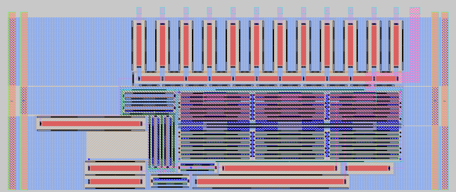
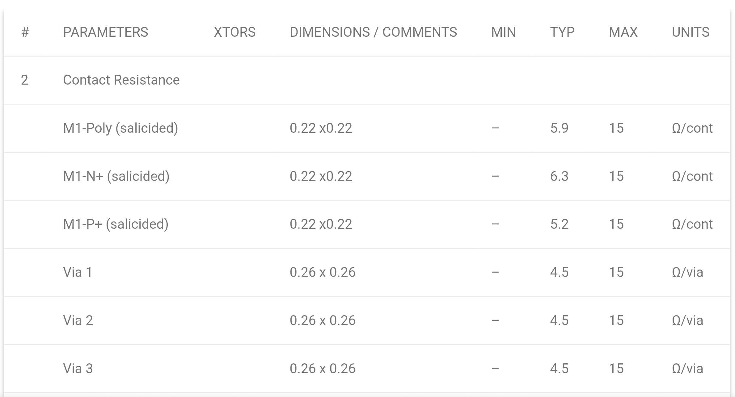
I'd still suggest putting the output drivers locally near it/harden them into the macro (or macro group if you group them again), unless math says a pathological librelane trace would cause substantially less than 1 ulp (LSB) of error even for the MSB resistor. I don't have the trace width and realistic upper limit of via count on hand, though, and also don't know (would have to eyeball) the value of your resistors. 4kΩ/8kΩ? IMO feels kinda dangerous if the vias are at the higher end of their range, 8kΩ/256 = 31.25Ω, compare to 4.5Ω/via (typ) to 15Ω/via (max):
Avatar
I have a ton of words I could say about the antenna rules, but none of them are appropriate for this chat. My die is ready (except for the art, but that’s not a functional component) and it looks like I’m going to have to allocate a week or more of my schedule to "fix antenna violations", just like last time.
7:18 p.m.
"Inserted 9768 Diodes" and its somehow still not enough
Avatar
Avatar
Tholin
Click to see attachment 🖼️
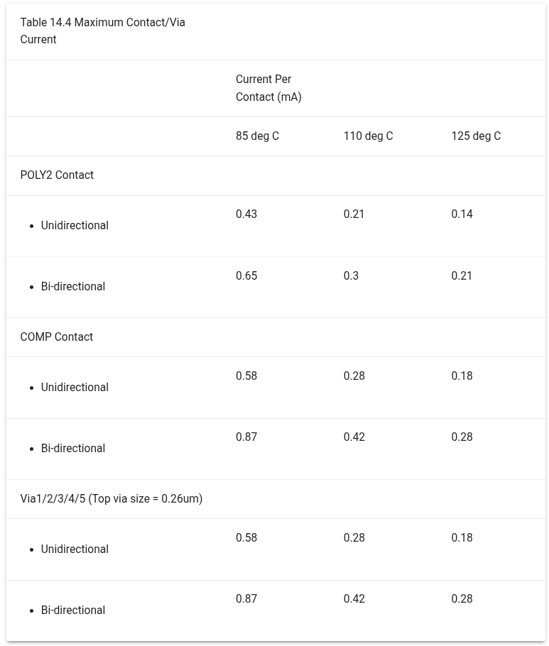
If it actually did tape out with just a single via in the resistor digital feed traces there, electromigration would have severely limited the life of the DACs; approximately it seems like mean time to failure is inversely proportional to the square of the current density (at given temperature).... https://gf180mcu-pdk.readthedocs.io/en/latest/physical_verification/design_manual/drm_14_2.html
Avatar
Avatar
Tholin
I have a ton of words I could say about the antenna rules, but none of them are appropriate for this chat. My die is ready (except for the art, but that’s not a functional component) and it looks like I’m going to have to allocate a week or more of my schedule to "fix antenna violations", just like last time.
Could maybe be feasible to teach the fixer to jog offenders up above the layer on which the antenna violation triggers?
Avatar
Detailed routing is currently on the 28th antenna repair iteration and the amount of violations is going up! Its making it worse trying to fix it!
Avatar
Avatar
namibj
I'd still suggest putting the output drivers locally near it/harden them into the macro (or macro group if you group them again), unless math says a pathological librelane trace would cause substantially less than 1 ulp (LSB) of error even for the MSB resistor. I don't have the trace width and realistic upper limit of via count on hand, though, and also don't know (would have to eyeball) the value of your resistors. 4kΩ/8kΩ? IMO feels kinda dangerous if the vias are at the higher end of their range, 8kΩ/256 = 31.25Ω, compare to 4.5Ω/via (typ) to 15Ω/via (max):
8k over 4k is right. Is that still too much current?
Avatar
Is there a librelane config variable I can use to override the contents of the synth_exclude.cells file with another list?
Avatar
Avatar
Tholin
8k over 4k is right. Is that still too much current?
5 volt / (8 kiloohm + 4 kiloohm) ➞ milliampere = 0.416667 mA [Current]
Avatar
Avatar
Tholin
3.3v
oh ok
3.3 volt / (8 kiloohm + 4 kiloohm) ➞ milliampere = 0.275 mA [Current]
Avatar
Much better
Avatar
still questionable if that part of the chip might be running hot
12:39 a.m.
remember you have more than just that one via involved
12:39 a.m.
like it shouldn't break for a few months at least
Avatar
Avatar
Tholin
New version of the DAC, this time without the 25mA static current consumption
what is the construction of the trunk-to-trunk segment joins, btw?
12:41 a.m.
many vias? continuos poly2?
Avatar
many vias
12:43 a.m.
The maximum current draw through the output stage is now 6mA
12:43 a.m.
That should spread pretty thin over the dozens of vias
12:44 a.m.
the resistor ladder's ends are also fitted with multiple vias each?
12:44 a.m.
I see 11 theoretical digits? Quite a lot....
12:46 a.m.
(I'm honestly just a bit sad that we're forced to use such wide resistors for the high sheet option; would be nice if we had one of the higher variants instead, but oh well... maybe in the future?)
Avatar
The output of the resistor ladder routes through a 20K resistor
Avatar
huh, a little bit strange given that the R-2R architecture is conveniently constant-impedance on it's own.
Avatar
The 20K is part of the inverting amplifier
Avatar
Last time, I taped out a NTSC test signal generator, though it could only do greyscale. This time, I’ll take a shot at composite color.
3:11 p.m.
The complicated analog circuitry I started designing for this isn’t done yet, but I realized I can go digital, actually.
3:11 p.m.
4 times the color burst frequency is 14.31818MHz, which is totally doable as a clock rate for a gf180 chip
3:12 p.m.
So I can generate 4 square waves with different phases entirely digitally and get 4 hues (edited)
💜 1
Avatar
Does anyone have a nix environment/flake/whatever-such around that would give me a working KLayout with working GDSFactory-based PCells as suitable for designs that get included into Run2?
👍 1
Avatar
Avatar
namibj
Does anyone have a nix environment/flake/whatever-such around that would give me a working KLayout with working GDSFactory-based PCells as suitable for designs that get included into Run2?
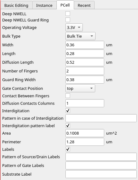
diff --git a/flake.nix b/flake.nix index 74f7449..feede55 100644 --- a/flake.nix +++ b/flake.nix @@ -75,6 +75,9 @@ # For logo generation pillow + + # For KLayout advanced PCells + gdsfactory ]; }); }

8:55 p.m.
It does not work as one can see.
8:58 p.m.
This is what I wanted to check out there; for my MUX2; and possibly a 3-finger variant for the special 4:1 MUX though that particular one likely without the bulk tie; tbh that's a bit sus even for the 2:1 MUX...
Avatar
is there an online 3d model view of the dies?
12:15 a.m.
the thinking is: cut a die, image the exposed cross section, then try to find the corisponding slice in the digital model
Avatar
Andrew Wingate 2026-06-30 1:08 a.m.
Hey all, Kindly reminder there is 10 hours left for the run 2 purchase deadline. https://www.crowdsupply.com/wafer-space/gf180mcu-run-2 GDS will be due in 2 weeks. Thanks!!
Fabricate 1,000 chips of your own design
Avatar
Need a moderator .. @Leo Moser (mole99) / @Tim 'mithro' Ansell / @Andrew Wingate ?
Avatar
Avatar
tnt
Need a moderator .. @Leo Moser (mole99) / @Tim 'mithro' Ansell / @Andrew Wingate ?
Leo Moser (mole99) 2026-06-30 6:52 p.m.
Done. Thanks!
👌 2
Avatar
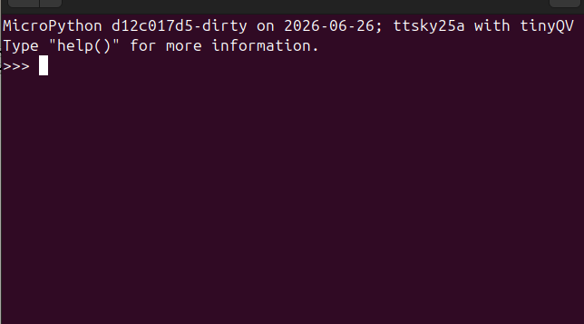
I've received some TinyQV chips, and I can confirm they are basically working! I've got Micropython running: https://hachyderm.io/@rebelmike/116840540971129298
Attached: 1 image It booted Micropython! Ignore the fact that says ttsky25a, that's just the build I had to hand. Currently UART RX not working but I suspect that's because the sky25a build configures that wrong.
🎉 5
🚀 2
waferspace 1
Avatar
Avatar
namibj
It does not work as one can see.
@Thomas Pluck 2.1 do you guys have a functioning nix shell flake with a KLayout where your nice PCells work ?
Avatar
I still have not created my project on the platform, but tbf, I can’t produce DRC-clean GDSIIs right now due to a bug in the Detailed Router antenna repair.
Avatar
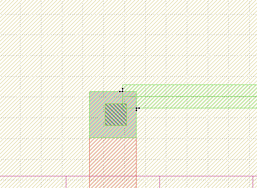
Librelane is connecting to this IO in a way that causes a DRC error
Avatar
Avatar
Tholin
Librelane is connecting to this IO in a way that causes a DRC error
Is that port on the routing grid?
Avatar
It should be
9:56 p.m.
FeatherLane uses the same routing grid dimensions as LibreLane
9:56 p.m.
At least, for this PDK
RebelMike started a thread. 2026-06-30 10:37 p.m.
Avatar
Avatar
Tholin
At least, for this PDK
So that's a port of the I/O cell, right? Or is that a custom macro port? The via looks a little off center. Is the via placed by the router or part of the cell/block? If the cell port is on the routing grid, is the cell placement also on the routing grid? Seeing as how the wire only intersects a portion of the port vertically, I have my doubts as to whether the port is actually on the routing grid. Note that the router will still try to route to ports that are off the routing grid, but routing is usually much cleaner if hard macros are designed with ports that are on the routing grid. I think librelane currently distributes ports evenly without regard to the routing grid and to the cell boundary which may not be a grid multiple. Maybe an enhancement would be helpful.
Exported 364 message(s)
Timezone: UTC+0