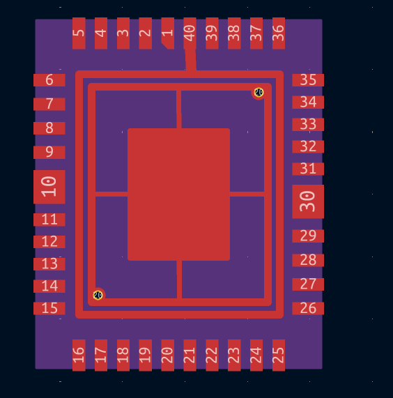
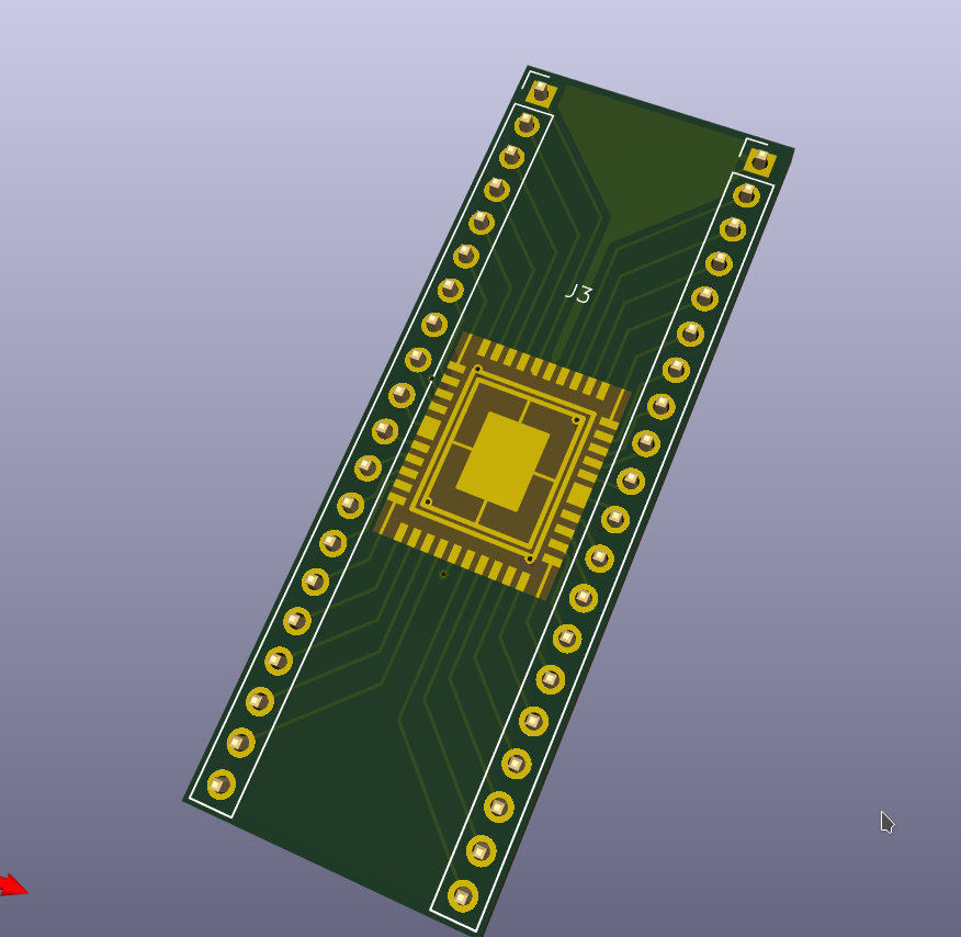
Yes, the pitch is 1mm as shown.
I hadn't realized how large the ring for the bonding wires was so there's a lot more room than I had thought.
All this is a bit of an exploration into what's the best form factor for:
ease of use
easiest for the wire bonders themselves
if you want many of them
I am open to suggestions.
I am seeing 64 pins?
Is that what we should be shooting for.
I was under the assumption there were no hard standards and was shooting for something that could cover most use cases while being easy for people to work with.
There were also some suggestions for this same kind of thing but with .1" spacing and the ability to breadboard.
Is there interest in that variation as well?
tnt
@Tim 'mithro' Ansell What's the die thickness ? Are they going through thinning ?
I was more making a visual model than anything concrete, just trying to engage some conversation and see if there are opinions so I may gather a consensus of sorts.
Relevant section. I believe I can design a COB footprint based on these dimensions. I also have diagrams for DIP-48 and DIP-64 carriers to reference if more pads are needed.(edited)
(sorry, I was just directed here by someone chatting about garage phabs and just wanted to say I'm a fan of your videos! I'll go back to being a normal person now)





 3
3


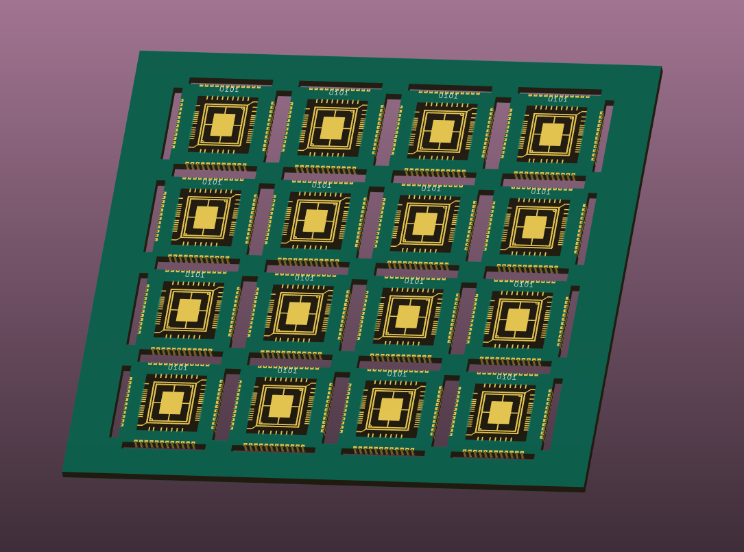
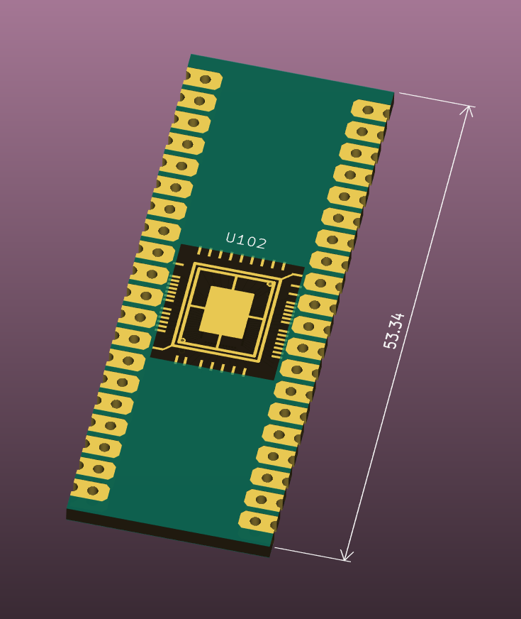

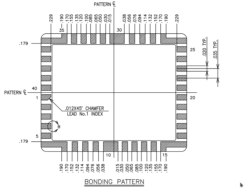
 1
1

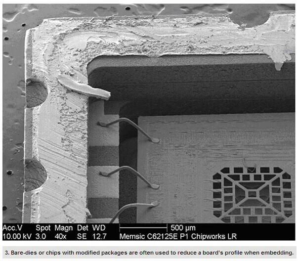

 1
1