Guild icon
wafer.space Community
🏗️ - Designing / cob
Channel for discussing chip-on-board packaging options for wafer.space bare die.
Between 2025-12-31 11:59 p.m. and 2026-02-01 12:00 a.m.
Avatar
Live Free Or Die ASIC
😂 1
👍 2
11:54 p.m.
😂 1
Avatar
Andrew Wingate 2026-01-07 8:06 p.m.
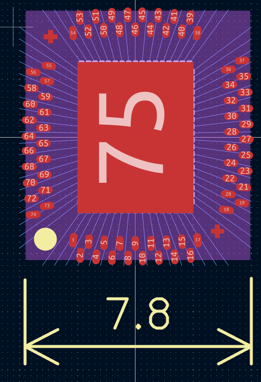
Hey @xianglin_pu, Le'ts just continue the discussion here if that's alright with you. Over the break or sometime, I camy up with this. Influenced in no small part to the work you have done. If you'd like to take a stab at making another version I would be happy to see it. These are some design rules https://drive.google.com/file/d/1touEQHWAOTon_98TdiVLKKqsQ8RJJ1tP/view Assume the die is 0.75mm thick. I have attached some drawings I sent a dicing house to get us some sample wafers diced for testing.
8:11 p.m.
I think the design constraints should be brought in a touch. Basically I would like for the cob to fit in between headers that are spaced at 0.6" like we would have for a DIP type chip. The carrier board would be 0.1" wider than what you see in these pictures. Let me know if you have any questions, I'll try my best to answer. Also, don't take the above picture as gospel, I only spent a few minutes playing around and just shared is all. Thanks and good luck!
❤️ 3
Avatar
Did my first attempts at making a COB footprint accidentally set the standard of using certain comment layers in KiCad for marking the pad locations and bond wires?
8:13 p.m.
I see everyone doing it now, and I’m curious.
Avatar
Avatar
Tholin
I see everyone doing it now, and I’m curious.
Andrew Wingate 2026-01-07 8:15 p.m.
My design was a derivative of yours ;) It does a good job of conveying lots of information. And @xianglin_pu's design was a derivative of mine I believe. Was well thought out. Thank you
👍 1
Avatar
Yeah, KiCad’s measurement tools let you quickly check if you are exceeding angle limits.
💜 1
Avatar
Andrew Wingate 2026-01-07 8:17 p.m.
Not only that, I feel like having a real drawing of the bonding scheme will pay dividends when we actually go to get quotes and wirebonding for real.
Avatar
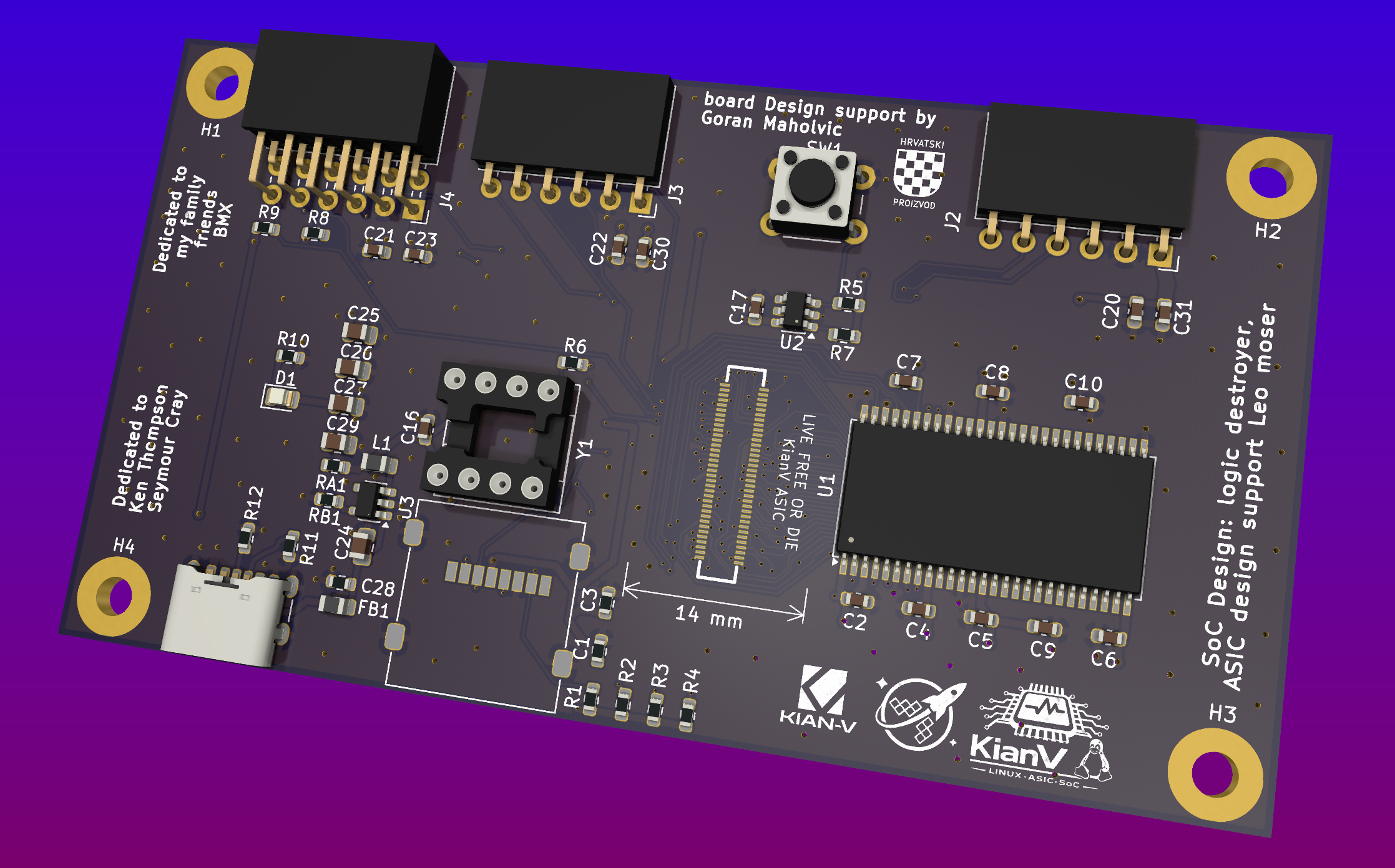
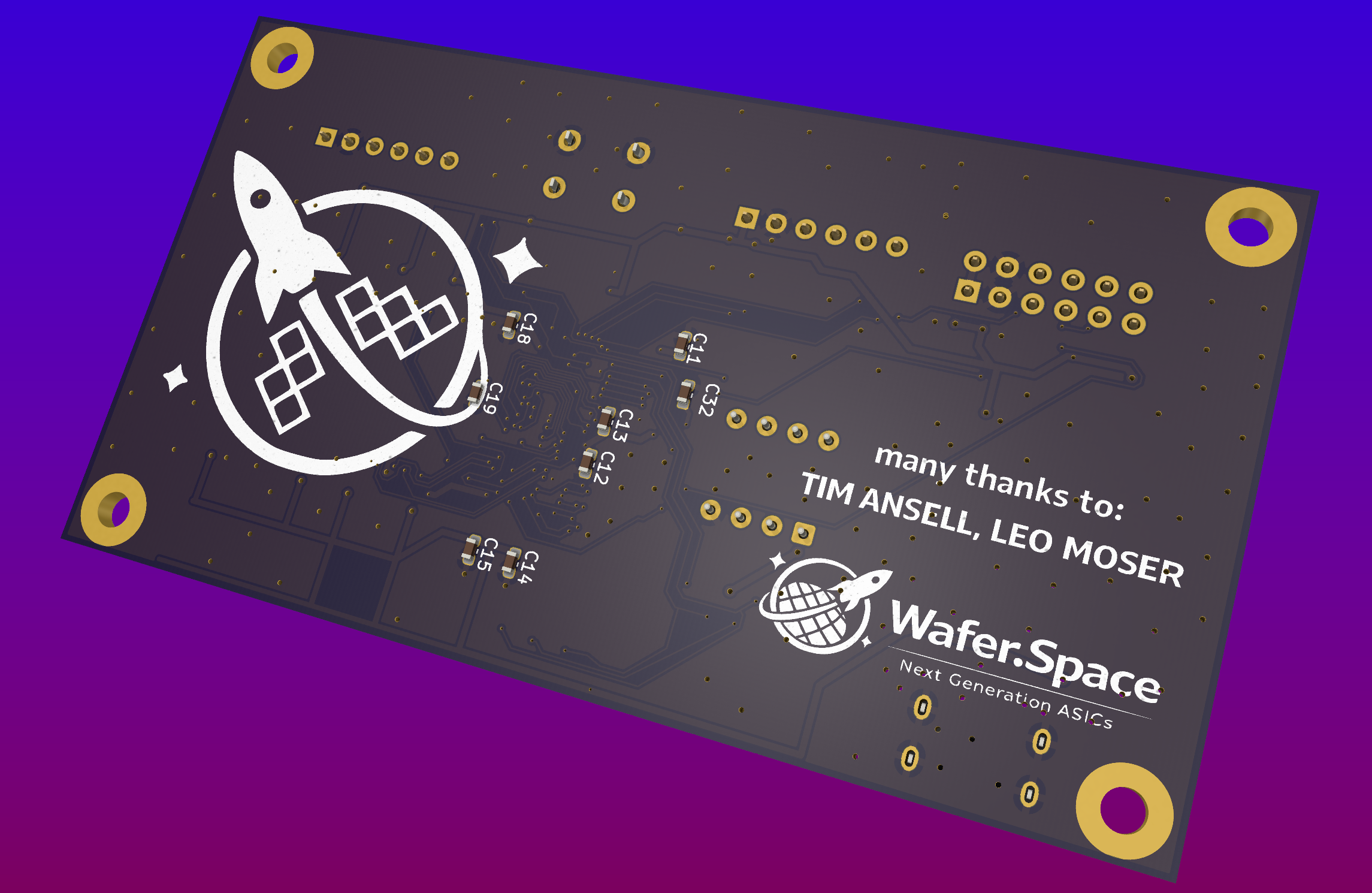
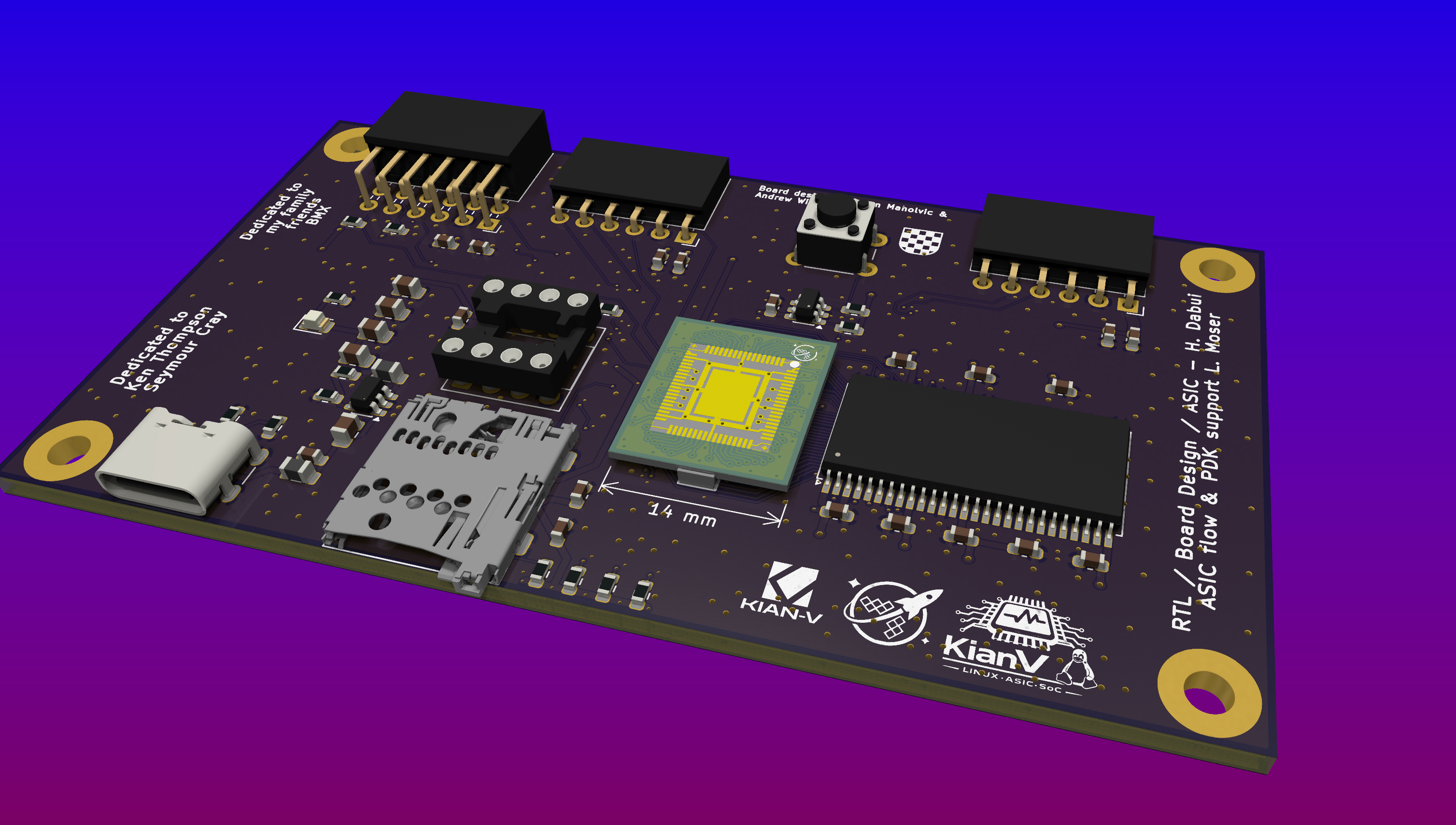
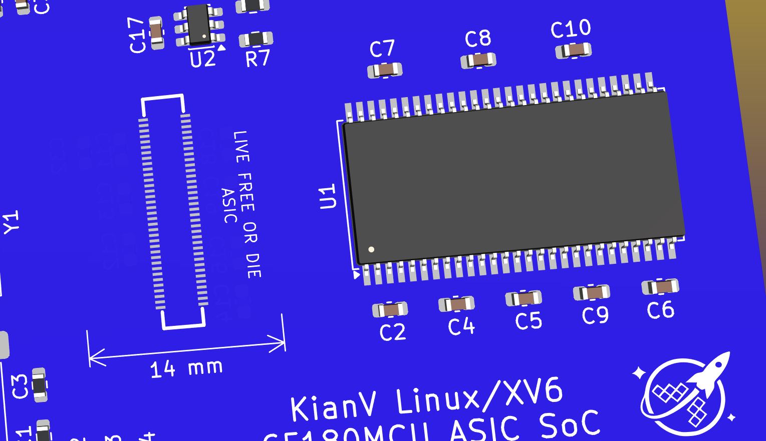
I’ve wired everything up now. @GoranMahovlic helped me a lot, especially with the SDRAM wiring and the connector. I don’t have much experience—this is my first real board—so I’m going to check the signals again and double-check the connector pinout. Then I’ll send it to a fab/assembly shop for soldering. I really wanted to finish this so I can continue with my next Linux SoC, StealthV.
🔥 1
❤️ 1
Avatar
Avatar
asic destroyer
I’ve wired everything up now. @GoranMahovlic helped me a lot, especially with the SDRAM wiring and the connector. I don’t have much experience—this is my first real board—so I’m going to check the signals again and double-check the connector pinout. Then I’ll send it to a fab/assembly shop for soldering. I really wanted to finish this so I can continue with my next Linux SoC, StealthV.
Awesome! That looks great!!
❤️ 1
Avatar
Thank you @Andrew Wingate
Avatar
Looks like a few GND vias are missing, so there’s a bit of rework to do, but it’s 95% finished
Avatar
I can buy from that store , based in Berlin, DIP-8 oscillators there. https://www.segor.de (edited)
Avatar
Avatar
asic destroyer
Thank you @Andrew Wingate
If your board is on github, you can stick that link into this site and get a web view of the board. Here is an example of a friend's board. https://kicanvas.org/?github=https%3A%2F%2Fgithub.com%2FCarlFK%2Fgeebee%2Ftree%2Fmain%2Fdell7212%2Fkicad%2Fbgpogo If you post it, I'll take a look at it if you'd like.
❤️ 1
Avatar
When it’s final, I’ll put it on GitHub.
👍 1
Avatar
Also side note: KiCanvas was helped to make real by @Tim 'mithro' Ansell Thanks Tim, I have used it a number of times
❤️ 2
Avatar
@Tim 'mithro' Ansell is always full of surprises.
💜 1
Avatar
@Andrew Wingate I sent you a zip file of the pcb
👍 1
Avatar
asic destroyer 2026-01-10 5:21 p.m.
5:22 p.m.
@Andrew Wingate I just sent you a new ZIP.
Avatar
Avatar
Andrew Wingate
Hey @xianglin_pu, Le'ts just continue the discussion here if that's alright with you. Over the break or sometime, I camy up with this. Influenced in no small part to the work you have done. If you'd like to take a stab at making another version I would be happy to see it. These are some design rules https://drive.google.com/file/d/1touEQHWAOTon_98TdiVLKKqsQ8RJJ1tP/view Assume the die is 0.75mm thick. I have attached some drawings I sent a dicing house to get us some sample wafers diced for testing.
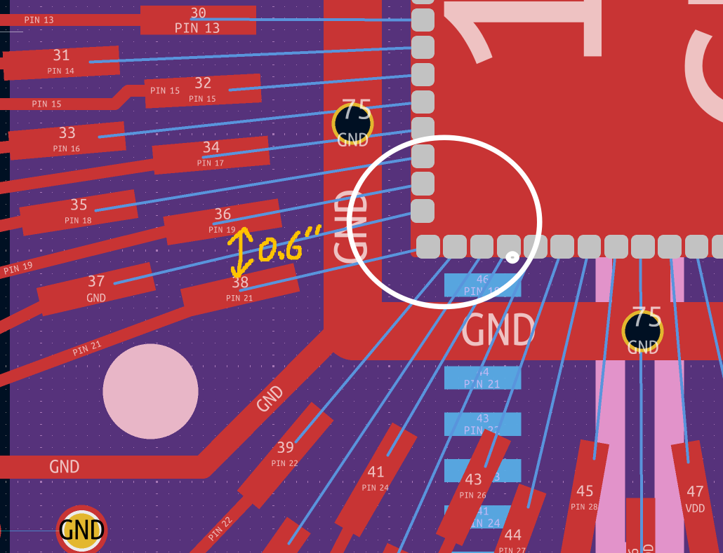
Thank you @Andrew Wingate for your information, it's helpful.😃 I am bit confused with "the cob to fit in between headers that are spaced at 0.6"", do you mean the clearance space between pads ? like I drawed below in yellow. Also I see the design rule for wire bonding, I noticed that the min bonding angle must >45 degree, I am not sure would the ones that circled in white also work ? I really appreciate your feedback, (edited)
Avatar
What is the status of the wire bonded breakout PCB layout? At some point, I need to fork it and derive a version of it that works with my custom pad ring, but I don’t know if I can do this yet.
Avatar
Avatar
Tholin
What is the status of the wire bonded breakout PCB layout? At some point, I need to fork it and derive a version of it that works with my custom pad ring, but I don’t know if I can do this yet.
Andrew Wingate 2026-01-24 6:28 a.m.
I am not sure I will be able to make any of the changes I had hoped for in time. @asic destroyer has also started designs with the layout as outlined currently. Unless @xianglin_pu or someone else puts something forward or says something very soon, I think we have what will be the first version
Avatar
Avatar
Andrew Wingate
I am not sure I will be able to make any of the changes I had hoped for in time. @asic destroyer has also started designs with the layout as outlined currently. Unless @xianglin_pu or someone else puts something forward or says something very soon, I think we have what will be the first version
asic destroyer 2026-01-24 8:39 a.m.
I hope you don’t change anything about the pinout.
👍 1
Avatar
Avatar
Andrew Wingate
Just assembled the first test COB. I think I pretty much like the form factor. With 70pins they hold on there pretty good. Some conversations with other people, they had mentioned mezzanine connectors to the a weak point, but these seem pretty solid. I think I'm pretty happy with them overall.
@Andrew Wingate ❤️
💜 3
Exported 27 message(s)
Timezone: UTC+0