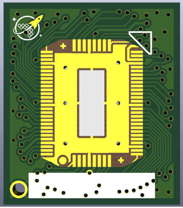
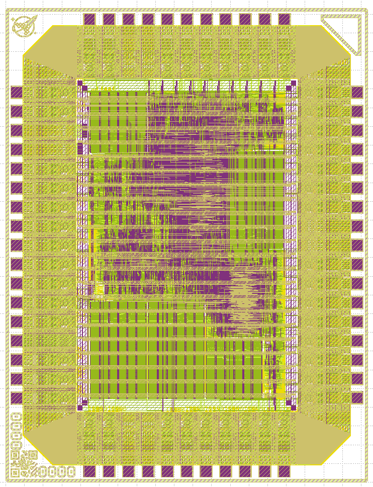
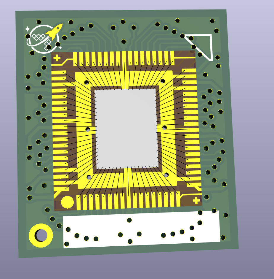
So the idea was to make it super obvious which way around to put the die (assuming you can see the markings on the die). This is what a run 2 die looks like. You are allowed to remove the wafer space logo, but not the arrow in the top right or the QR code in the bottom left:
6:32 p.m.
So things are now in the same position on the CoB and the die. The arrow always matches, and the wafer space logo matches providing the user hasn't removed it.
Pin 1 is in the bottom left, and is indicated by QR code on the die and by the circle on the CoB. I see there's potential for this to be confusing because the arrow and logo markings are a bit more obvious - but as everything is now the same way round as it is in klayout/OpenROAD it is hopefully unlikely that users would get confused.
6:38 p.m.
That said - there's potential for making the arrow smaller and/or the pin 1 circle bigger, or having some other marking to make it more obvious.
6:45 p.m.
Or were you referring to pin 1 on the mezzanine connector? It does seem like it would be a good idea to put a little arrow next to that!
And it would be good to update the standard breakouts so the wafer space logo on them is the same way up as the wafer space logo on the CoB
@RebelMike - making sure there is no symmetry is always good, prevents people from putting things around the wrong way.
1:20 a.m.
I was hoping for something like a single pin header (on the motherboard) with an associated hole in the CoB corner would be a useful keying type thing.
1:21 a.m.
Also, I thought that the wafer.space logo was required for wafer.space doing the CoB bonding? @Leo Moser (mole99) - did that get lost?
RebelMike
That said - there's potential for making the arrow smaller and/or the pin 1 circle bigger, or having some other marking to make it more obvious.
Alright, got to a place where I can sit and think for a moment.
I'm still playing with a few things.
The triangle was an unfortunate inclusion. It's a NONshape meant to be nothing, but @Leo Moser (mole99) cannot verify nothing, only something, that was the something compromise.
I'm playing with it a bit, but where I'm leaning is to have a qr looking shape in the bottom left, rocket stays where its at and that would have all 3 corners that are required to all be marked.
1:23 a.m.
Or maybe @Tim 'mithro' Ansell is more on the right track. gimme a moment and I'll post something
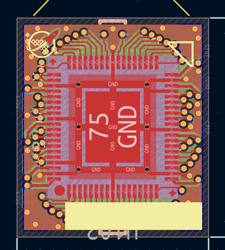
@here what do you think about having a large PTH as the pin1 marker.
That allows someone to solder in a header pin into their motherboard that would force orientation.
@RebelMike One thing about the circle in the wirebonding footprint is that it will likely be covered in black and you won't be able to see it anymore. ?Ideally? this sits far enough outside to stay clear of gunk (I made it much larger than it needs to be to account for process variabilities and things likely being done by hand)
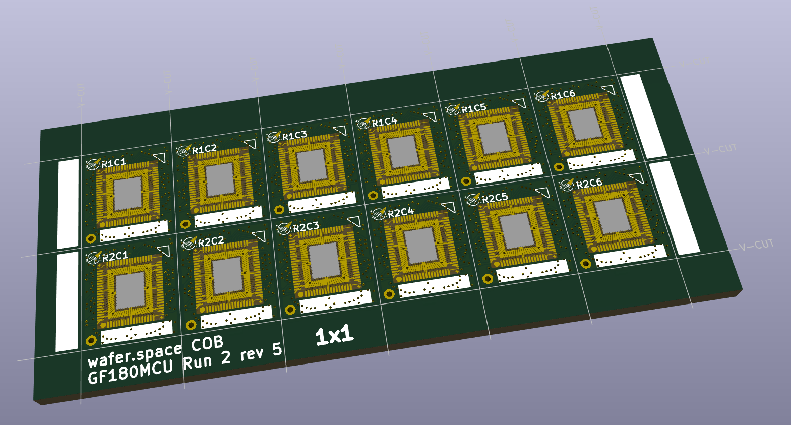
ok, just made a panel out of this, we can sort things later if need be, but think we're close enough for the preliminary runs.
-# @stuart panel can be found in same place
Wire bonded chip on board PCB designs. Contribute to wafer-space/chip-on-board-wire-bonded-pcbs development by creating an account on GitHub.
2:06 a.m.
Andrew Wingate
@here what do you think about having a large PTH as the pin1 marker.
That allows someone to solder in a header pin into their motherboard that would force orientation.
@RebelMike One thing about the circle in the wirebonding footprint is that it will likely be covered in black and you won't be able to see it anymore. ?Ideally? this sits far enough outside to stay clear of gunk (I made it much larger than it needs to be to account for process variabilities and things likely being done by hand)
I'd still put a "1" in silk screen next to it. There are so many other "features" ( triangle / logo ) that it could be confusing. Especially the triangle which is 180 deg appart and thus would allow to plug the board in reverse and the triangle is often used as pin 1 markers on CPU and such.
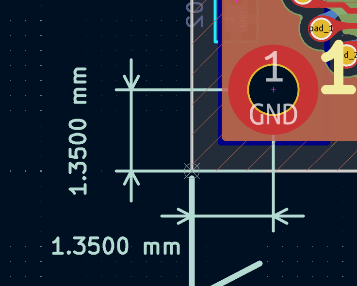
OK, to avoid needing significant work on the 0p5x1, could we reduce the size to 1.3mm? The hole can still be 0.8mm, just reduce the thickness of the exposed copper surround. And then push it closer to the corner, so the centre is 1.25mm away from the edge cut on both sides.
Hmm, and if people are going to stick a standard 0.1" header pin through it rather than just using it as a marker, 0.8mm hole is pretty tight. Maybe should be 1mm hole?
So revised suggestion: 1.4mm size, 1mm hole, 1.2mm from the edge cut:
ok, just made a panel out of this, we can sort things later if need be, but think we're close enough for the preliminary runs.
-# @stuart panel can be found in same place
panel.zip I can stop making the rev ones if you want, they just have all the files that is the older versions. There was a time in the past we wished we could look back and see what something was for a certain run.
Andrew Wingate
panel.zip I can stop making the rev ones if you want, they just have all the files that is the older versions. There was a time in the past we wished we could look back and see what something was for a certain run.
It maybe makes it a bit more obvious so it's probably worth keeping some. It might also be handy for a ground clip when probing? It is also useful as a big ground via given it replaced a few in this corner.
10:40 a.m.
Not sure if the panels you're currently making are likely to make it out to people, but ideally it would be nice to finalise the position of the hole before any are made, to avoid inconsistencies.
I've made PRs for consistently adding a pin 1 hole to all the CoB variants. The quarter slot PR also picks up the required changes from the previous PRs.
RebelMike
Not sure if the panels you're currently making are likely to make it out to people, but ideally it would be nice to finalise the position of the hole before any are made, to avoid inconsistencies.
Sorry for the delay, after my meeting last night I think I fell asleep in front of my computer for a moment.
This is where I put it on the 1x1, I'll review them as I panelize.
Thanks again @RebelMike
Yeah, I appreciate you have a lot going on!
If possible though, do take a look at how it fits on the 0p5x1 before settling on anything - it’s quite busy in that corner (and pretty much everywhere!)
1
Tim 'mithro' Ansell
Also, I thought that the wafer.space logo was required for wafer.space doing the CoB bonding? @Leo Moser (mole99) - did that get lost?
Back then we decided on the QR-code and the triangle as being mandatory. The wafer.space logo can be swapped out with a different logo or removed completely.
Leo Moser (mole99)
Back then we decided on the QR-code and the triangle as being mandatory. The wafer.space logo can be swapped out with a different logo or removed completely.
@Leo Moser (mole99) - I think the wafer.space logo being mandatory when doing wafer.space CoB bonding is probably something we want to do? (For people doing bare die, they can do whatever they want....)
I'm pretty sure the idea was that diagonal corners to never be the same (filled verse unfilled) so it didn't matter if you could actually understand/recognize the graphics -- you just needed to determine "is there something there or not".
Am I mistaken?
Tim 'mithro' Ansell
@Leo Moser (mole99) - I think the wafer.space logo being mandatory when doing wafer.space CoB bonding is probably something we want to do? (For people doing bare die, they can do whatever they want....)
I'm pretty sure the idea was that diagonal corners to never be the same (filled verse unfilled) so it didn't matter if you could actually understand/recognize the graphics -- you just needed to determine "is there something there or not".
Am I mistaken?
We discussed this in a meeting (you, Andrew, I) earlier this year before Run 2, and the resolution was that the QR code with the human readable ID in the bottom left corner, and the triangle in the top right is sufficient to determine the orientation.
We decided against making the wafer.space logo mandatory. I updated the precheck to verify the location of the ID and the triangle before Run 2.
Leo Moser (mole99)
We discussed this in a meeting (you, Andrew, I) earlier this year before Run 2, and the resolution was that the QR code with the human readable ID in the bottom left corner, and the triangle in the top right is sufficient to determine the orientation.
We decided against making the wafer.space logo mandatory. I updated the precheck to verify the location of the ID and the triangle before Run 2.
@Leo Moser (mole99) / @Andrew Wingate - I'm hopeless at "spacial" stuff -- Does the QR code and triangle provide enough detail that no matter what is in the other corners, it is impossible to accidentally get them around the wrong way?
No. They are opposite corners meaning you can easily swap them.
9:56 p.m.
But even if you made the WS logo mandatory, you would also need to mandate the 4th corner to remain empty ... else it wouldn't help as you could have "something" in all 4 corners and you'd need to identify which is which to know die orientation.
10:00 p.m.
I was trying to see the corners in the pics from run #2 but they are way too blurry for that
Maybe you could mandate that the top left contains at least some minimum amount of metal, so people could swap it with their own logo if they like, and the bottom right must be empty?
@tnt - The "corner triangle" is suppose to look empty.
1
tnt
But even if you made the WS logo mandatory, you would also need to mandate the 4th corner to remain empty ... else it wouldn't help as you could have "something" in all 4 corners and you'd need to identify which is which to know die orientation.
Ok, so I wanted the corner opposite the QR code to be blank, but I am told there is no way to verify a nothing, only a shape, the shape closest to nothing is what @Leo Moser (mole99) put in the opposite corner.
@Andrew Wingate - The idea being that if you had the die around the wrong way, it would be pretty clear because there would either be something (IE a qrcode), or nothing (IE the triangle)?
Tim 'mithro' Ansell
@Andrew Wingate - The idea being that if you had the die around the wrong way, it would be pretty clear because there would either be something (IE a qrcode), or nothing (IE the triangle)?




 1
 1