
wafer.space Community
Information / general
Welcome to wafer.space - documentation at wafer.space github - buy at buy.wafer.space - archives at discord.wafer.space
Between 2025-10-31 11:59 p.m. and 2025-12-01 12:00 a.m.


 2
2

maglef/ that is DRC clean and points to the GDS data for the SRAM. That is the appropriate one to have in the layout while running full DRC.maglef/ that is DRC clean and points to the GDS data for the SRAM. That is the appropriate one to have in the layout while running full DRC. SramCore from the default DRC rules. This way all SRAM macros (and future generated ones) won't result in any violations. We should still check the layout with the KLayout rules, of course.
I will try to blackbox the foundry SRAMs for now, I even created a LibreLane PR for that some time ago: https://github.com/librelane/librelane/pull/786
 2
2_CDNS_ also fixes the issue for the SRAMs.
 1
1_CDNS_ also fixes the issue for the SRAMs. flatglob "*_CDNS_*" so that this would be taken care of by default for anyone with a sufficiently new version of magic. But I don't think that will solve the issue with the SRAMs, because the "CDNS" string is a result of using Cadence pcells, and the SRAM module cells are not pcells.flatglob "*_CDNS_*" so that this would be taken care of by default for anyone with a sufficiently new version of magic. But I don't think that will solve the issue with the SRAMs, because the "CDNS" string is a result of using Cadence pcells, and the SRAM module cells are not pcells. 
 3
3 3 3
3 3 1 1
1 1 2 1 3
2 1 3

 2 3 4
2 3 4 2
2
")
")
5'hxx: begin
  io_oe_sel = designname_oe;
  io_out_sel = designname_out;
  io_cs_sel = designname_cs;
  etc
(edited) 2 1 1 1
1 1")
")

 1 3
1 3
 1
1") 1
1")
 1
1")
")


")
") 1
1 2
2 1 1
1 1")
")


 3
3")
 1 3 2
1 3 2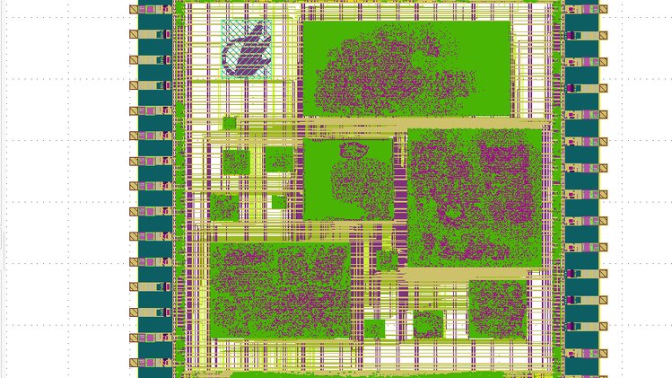 2 2
2 2") 1 3 4
1 3 4 Let me check...
gf180mcu_fd_io__dvss is used for all ground pads instead of my modified gf180mcu_ws_io__dvss which has pins on two metal layers.gf180mcu_ws_io__dvss for both horizontal and vertical I/O rows. 1
1 1
1 2 1
2 1 3 1
3 1 2
2
IInto the pad (going out of the chip) 1 3
1 3 3
3
") 3
3 roughly GBA-competitive in terms of graphics and CPU
inout ports yet, maybe you need to convince OpenROAD's GRT/DRT in some way to do that.ef bi IO that have the analog port added and see if it connects better to that. 1 1
Once we have a confirmed working 3.3V stdcell library, we can discuss setting it as the default for gf180mcu.PDK_ROOT and PDK and pass the rcfile to magic? 1
1PDK_ROOT and PDK and pass the rcfile to magic?
Yeah, 3.3V I/Os would also be great!magic: ## Open magic with the gf180mcuD PDK
PDK_ROOT=${PDK_ROOT} PDK=${PDK} magic -rcfile ${PDK_ROOT}/${PDK}/libs.tech/magic/gf180mcuD.magicrc
.PHONY: magic
This should work.gf180mcu_fd_io__bi_24t, flattened some of it and just deleted the DUALGATE layer. Next step would’ve been to go through and shrink the transistor lengths, since the 3.3V transistors have a way shorter minimum length. Note that this produces a 3.3V only pad, not a pad with separate core and IO voltage supporting both. 1 1 1signal bidirectionalare actually duplicates of ports that do have those parameters. )X_ _X
_X X_ 2 1 1
1 1FIXED_BBOX is set. 2
2set_false_path -from [get_ports {io_oe_.*}] and so on, but no luck.set_false_path -from [get_ports {io_oe_*}]?ports are external pads, so if you're running that on the top level, the ports are the actual pads since the top level include the IO cells. (edited)[ get_pins "*pad/OE" ] or something.set_false_path -from [get_ports {design_sel_*}]")
module falsepath_anchor (
    input  wire i,
    output wire z
);

`ifdef GF180MCU

(* keep *)
gf180mcu_fd_sc_mcu9t5v0__clkbuf_1 magic_falsepath_anchor_u (
    .I (i),
    .Z (z)
);

`else

assign z = i;

`endif

endmodule
and then just glob them out in the .sdc:
# Apply RTL-inserted false path constraints (setup/hold only, still constrain slew)
set_false_path -setup -hold -through [get_pins *.magic_falsepath_anchor_u/Z]
It's dirty but it makes the constraints a bit less fragile because you don't have to update them when hierarchy changes. Also I think paths through PD/PU can pretty much universally be falsepathed as the slew on the pad due to pulls is so slow.DNS_PROBE_FINISHED_NXDOMAIN
DNS_PROBE_FINISHED_NXDOMAIN  1
1") 1
1 3
3convert.py and remove the parts that downscales from 8bpc to 2bpc, and extend the ROM word length from 6 bits to 24 bits8:4 with RGB555 components then I could afford 3 analog pads
")
 1
1PAD_CELL_LIBRARY doesn't work, can't do that at all because if a glob called from the default config doesn't match any file, it's a fatal error, even if you try to later override that config key in your config ...PAD_CELL_LIBRARY be gf180mcu_fd_io and then override each key manually.glob returning no file not be an error would be good 1PAD_ config to be there at all and not in the gf180mcu_fd_io/config.tcl ? (edited) I have twenty 512x8 blocks, and my current setup is a ring around the logic cells. Pretty sure I have them all backwards at the moment though, and I have a bunch of slew/cap violations at the moment (and some other broken stuff too)
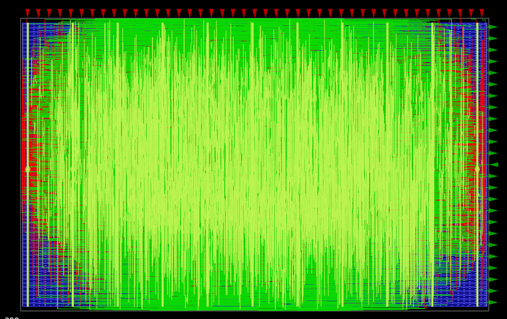
Seeing how little logic there actually is, I might condense the blocks closer to help with timing issues
I have twenty 512x8 blocks, and my current setup is a ring around the logic cells. Pretty sure I have them all backwards at the moment though, and I have a bunch of slew/cap violations at the moment (and some other broken stuff too)
Seeing how little logic there actually is, I might condense the blocks closer to help with timing issues") 2
I have twenty 512x8 blocks, and my current setup is a ring around the logic cells. Pretty sure I have them all backwards at the moment though, and I have a bunch of slew/cap violations at the moment (and some other broken stuff too)
Seeing how little logic there actually is, I might condense the blocks closer to help with timing issues 1
2
I have twenty 512x8 blocks, and my current setup is a ring around the logic cells. Pretty sure I have them all backwards at the moment though, and I have a bunch of slew/cap violations at the moment (and some other broken stuff too)
Seeing how little logic there actually is, I might condense the blocks closer to help with timing issues 1")
 1 1 1
I have twenty 512x8 blocks, and my current setup is a ring around the logic cells. Pretty sure I have them all backwards at the moment though, and I have a bunch of slew/cap violations at the moment (and some other broken stuff too)
Seeing how little logic there actually is, I might condense the blocks closer to help with timing issues 1
1 1 1
I have twenty 512x8 blocks, and my current setup is a ring around the logic cells. Pretty sure I have them all backwards at the moment though, and I have a bunch of slew/cap violations at the moment (and some other broken stuff too)
Seeing how little logic there actually is, I might condense the blocks closer to help with timing issues 1
 ️ Draft PR - For Feedback Only
This PR is NOT intended to be merged. It is shared purely to gather early feedback on the design and implementation approach for an API server that wraps the prechec... 1 1
️ Draft PR - For Feedback Only
This PR is NOT intended to be merged. It is shared purely to gather early feedback on the design and implementation approach for an API server that wraps the prechec... 1 1")
 2 1
2 1")
")

")
")


")
")
")
")
")
")
