wafer.space Community
Information / general
Welcome to wafer.space - documentation at wafer.space github - buy at buy.wafer.space - archives at discord.wafer.space
Between 2025-11-30 11:59 p.m. and 2026-01-01 12:00 a.m.




hd one from sky130. Price is ~ 1500 EUR per sq mm for ~ 40 dies. (edited)
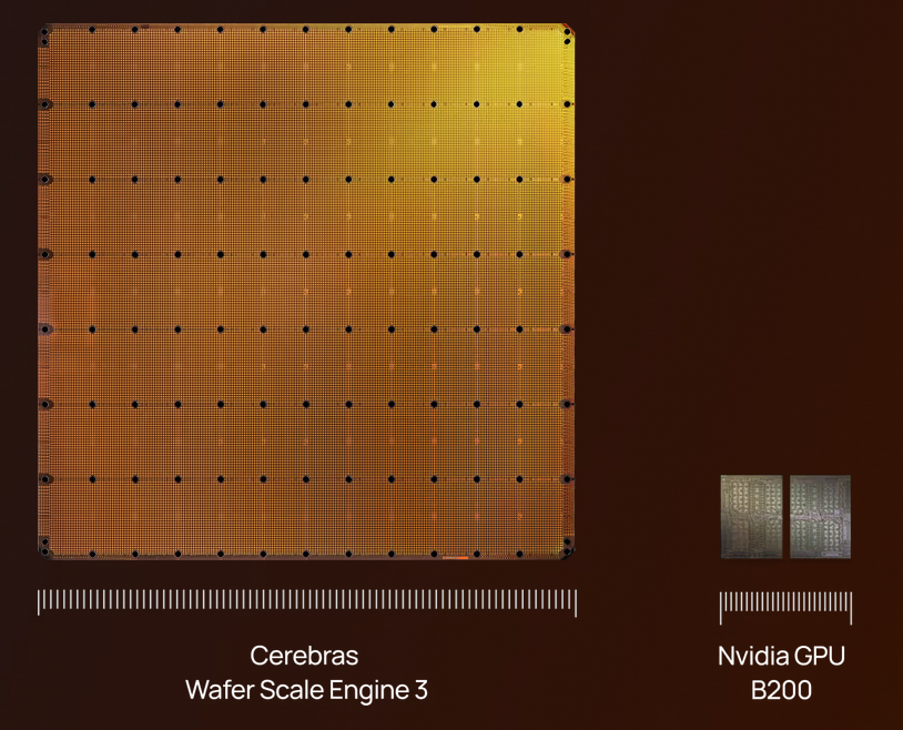

 I'm sure there are tons of weird issues like power distribution and timing and such, but could be a fun way to abuse an older node like 180nm
 1
1
 1 I'm sure there are tons of weird issues like power distribution and timing and such, but could be a fun way to abuse an older node like 180nm
  1
1


invz in the gf180mcu_fd_sc_mcu7t5v0 library.


github.com/[...]/blob/main/[...]). It could be a bit dangerous to use it as such, as they may change with time. For example, if some error is found in the precheck and there's a need to update it and rerun the check, the files may not be same anymore.
A simple fix would be to encourage users to update files that are commit-referred instead, like github.com/[...]/blob/39306415f62fd6e74851dbc5f0dc57ea608af3f3/[...], which are static
DIODE_ON_PORTS parameter.
If those are fanout related, make sure DESIGN_REPAIR_TIE_FANOUT is set to true.
Maybe adjust the DESIGN_REPAIR_MAX_CAP_PCT setting. Maybe counter-intuitive, but a higher setting may decrease the ratio by increasing the gate area. On the other hand, a lower setting may, decrease the wiring area.both for DIODE_ON_PORTS. Does that make a difference/something you want?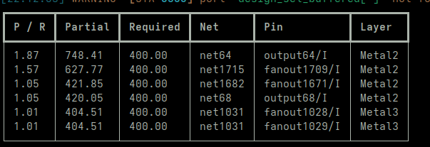
 1
1github.com/[...]/blob/main/[...]). It could be a bit dangerous to use it as such, as they may change with time. For example, if some error is found in the precheck and there's a need to update it and rerun the check, the files may not be same anymore.
A simple fix would be to encourage users to update files that are commit-referred instead, like github.com/[...]/blob/39306415f62fd6e74851dbc5f0dc57ea608af3f3/[...], which are static  2
2
  substituting_steps:
    +OpenROAD.RepairAntennas: Odb.InsertECODiodes
and I’ll report back in ~30 minutesSecurity validation failed: URL validation failed: Invalid file size: 0 bytes substituting_steps:
+OpenROAD.RepairAntennas: Odb.InsertECODiodes
and I’ll report back in ~30 minutes OpenROAD.DetailedRouting after that (edited)Security validation failed: URL validation failed: Invalid file size: 0 bytes [GPL-0305] RePlAce diverged during gradient descent calculating, resulting in an invalid step length (inf or NaN). but if the max fanout constraint in the config is changed from 7 to 6, it passes (before failing due to routing congestion).
Maybe also a fun benchmark case.[GPL-0305] RePlAce diverged during gradient descent calculating, resulting in an invalid step length (inf or NaN). but if the max fanout constraint in the config is changed from 7 to 6, it passes (before failing due to routing congestion).
Maybe also a fun benchmark case. [GPL-0305] RePlAce diverged during gradient descent calculating, resulting in an invalid step length (inf or NaN). but if the max fanout constraint in the config is changed from 7 to 6, it passes (before failing due to routing congestion).
Maybe also a fun benchmark case. 1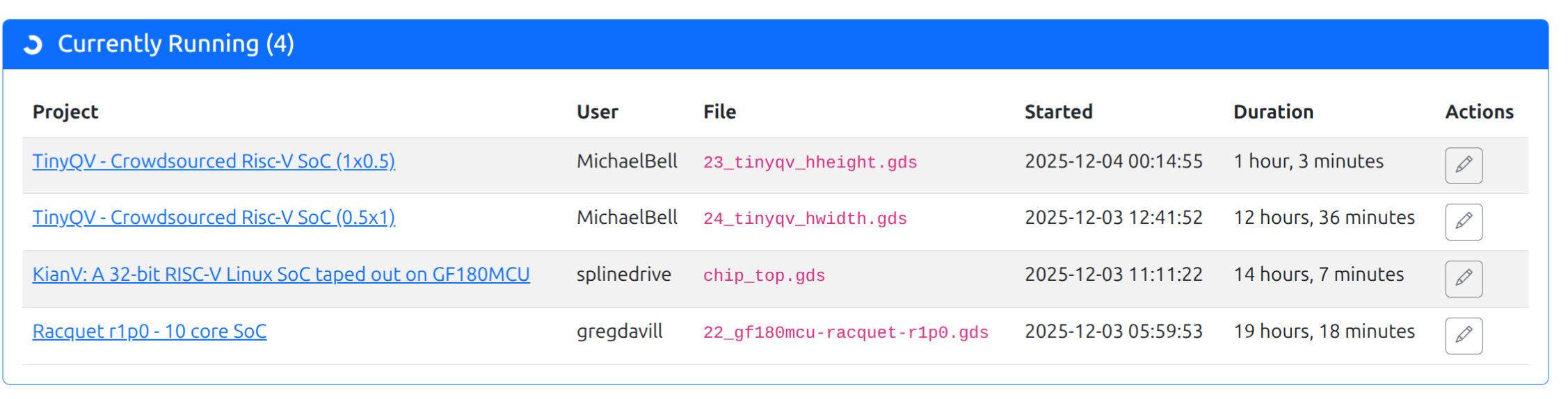
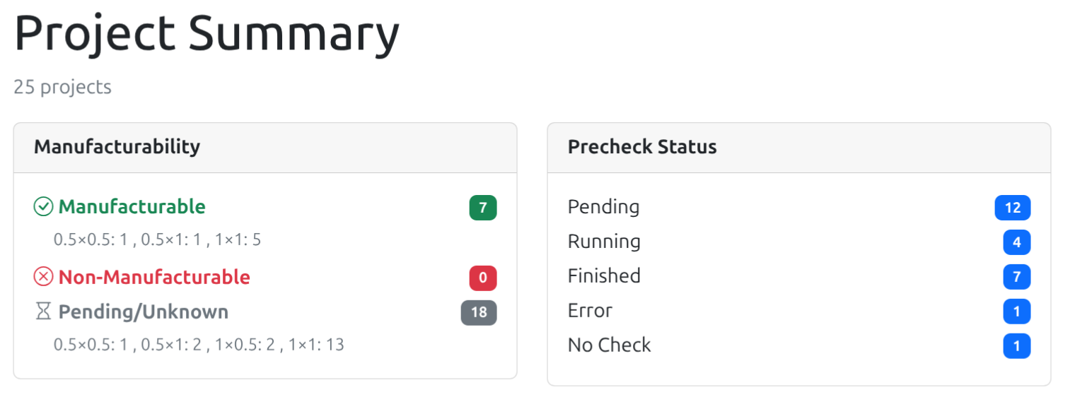
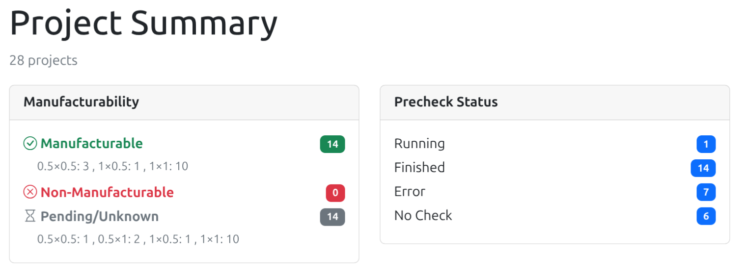 1 2 1
1 2 1invz cell is the equivalent of the GF 5V 7 track cell of the same name (I changed pin names to match your conventions), and the dfsrtp cell is the equivalent of the GF 5V 7 track cell gf180mcu_fd_sc_mcu7t5v0__dffrsnq_2.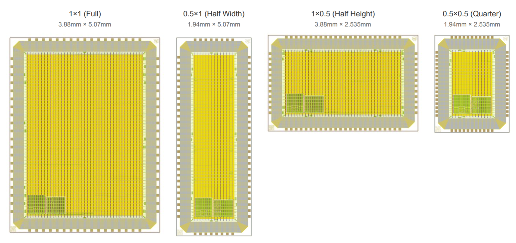
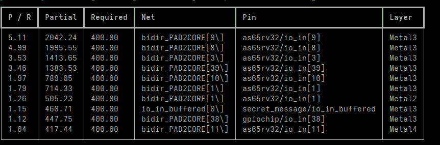


gds readonly true / gds read xxx.gds / writeall and this will rewrite mag views for all the cells in the GDS that was read.maglef are done. But @Tim Edwards would know 
inout for the analog signals and those should be connected to your newly defined PAD signal on the analog pins. (edited)rm -rf librelane/runs && make librelane did it occur to me that I could’ve just re-run the antenna check on the existing GDSII...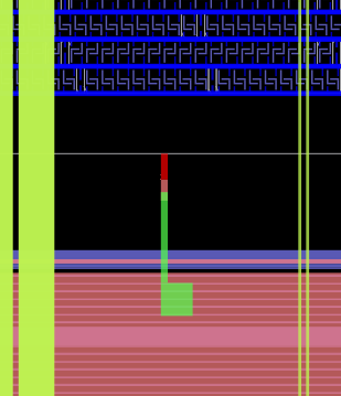



gds readonly true / gds read xxx.gds / writeall and this will rewrite mag views for all the cells in the GDS that was read. LEFclass, LEFsite and LEFsymmetry properties, so ensure they are preserved from the old mag files.LEFclass, LEFsite and LEFsymmetry properties, so ensure they are preserved from the old mag files.  1 1
1 1
nix shell github:librelane/librelane/dev
and then run the synthesis flow with
librelane librelane/config.yaml --pdk ${PDK} --pdk-root ${PDK_ROOT}.
Set PDK_ROOT to some directory and then Librelane should download the PDK. At least for me this yielded better results that helped me debug the design (edited)nix shell github:librelane/librelane/dev
and then run the synthesis flow with
librelane librelane/config.yaml --pdk ${PDK} --pdk-root ${PDK_ROOT}.
Set PDK_ROOT to some directory and then Librelane should download the PDK. At least for me this yielded better results that helped me debug the design (edited)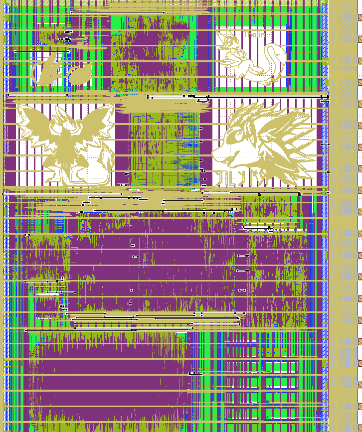
--manual-pdk option to librelaneABC: Setting driving cell to be "gf180mcu_as_sc_mcu7t3v3__inv_2/Y".
ABC: Setting output load to be 72.910004.
ABC: + source /home/tim/gits/gf180mcu_ocd_openframe/librelane/runs/RUN_2025-12-05_13-00-18/06-yosys-s
ynthesis/AREA_0.abc
ABC: Error: The network is combinational.
ABC: Cannot find the default PI driving cell (gf180mcu_as_sc_mcu7t3v3__inv_2/Y) in the library.n_diode | n_diode ... cc @Leo Moser (mole99) 1
1 No libs found for macro flow.py:698
gf180mcu_ocd_ip_sram__sram256x8m8wm1 at corner
max_ff_n40C_5v50. The module will be black-boxed.
But I am not specifying 5V anywhere. Where is this corner name coming from? My MACROS section specifies the .lib files for the SRAMs as, e.g., tt_025C_3v30. No libs found for macro flow.py:698
gf180mcu_ocd_ip_sram__sram256x8m8wm1 at corner
max_ff_n40C_5v50. The module will be black-boxed.
But I am not specifying 5V anywhere. Where is this corner name coming from? My MACROS section specifies the .lib files for the SRAMs as, e.g., tt_025C_3v30. STA_CORNERS, LIB and DEFAULT_CORNER.LIB is not set, the pdk_compat functionality in LibreLane will set it to these values: https://github.com/librelane/librelane/blob/d8b98532399f6eaa230e44e4a505bd653c10dd71/librelane/config/pdk_compat.py#L294 1 1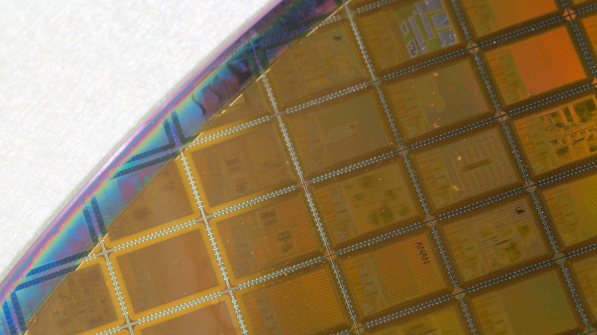 3
3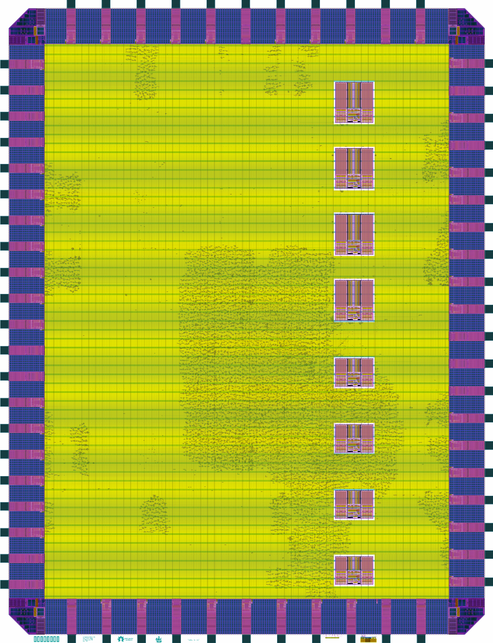
 2
2 3 -- Probably a terrible idea.
 2
2 ♂️
♂️ 1
1

DRT_ANTENNA_REPAIR_ITERS and
DRT_ANTENNA_MARGIN or anything else?
nix shell github:librelane/librelane/dev
and then run the synthesis flow with
librelane librelane/config.yaml --pdk ${PDK} --pdk-root ${PDK_ROOT}.
Set PDK_ROOT to some directory and then Librelane should download the PDK. At least for me this yielded better results that helped me debug the design (edited)dev branch of LibreLane and the "classic" flow. For the top-level build, we are using the LibreLane version from the nix-shell and the "chip" flow. From our POV this seems to work better for the macros in terms of timing and antenna violations. However, tbh, we do not really understand why. But there is nothing against this approach, right? (edited)
LAYER Via1
  RECT 13.645 1.690 13.905 1.950 ;
which worked fine (no DRC errors generated during routing). Not sure if it makes more sense to put it under the SN pin PORT record. I think I can have magic output via records where vias are sitting inside a port boundary. Until then, these lines have to be added manually.LAYER Via1
RECT 13.645 1.690 13.905 1.950 ;
which worked fine (no DRC errors generated during routing). Not sure if it makes more sense to put it under the SN pin PORT record. I think I can have magic output via records where vias are sitting inside a port boundary. Until then, these lines have to be added manually. FP_IO_HLAYER / FP_IO_VLAYERio_in[13] and it seems routed to several modules, but them go un-used in several of those ...pmetal_factor: 0.54
agate: 0.396
ametal_eff: 3451.0752
pmetal: 6390.88
max_ratio_eff: 5324.8
ratio: 8714.83636364
diode_factors: (6000)
adiodes: (0.8208)
max_ratio: 4003451.0752 / 0.396 = 8714.83636364 which is what it reports.
But it also sees the diodes 0.8208 which is correct for 2 antenna diodes cells connected on that segment.
But then the ratio should be 3451.0752 / (0.396 + 15 * 0.8208) = 271.6 which is not an error.ratio = perim_area / (gate_area + MF * diode_area) < 400(perim_area / gate_area) < 400 + (400 * MF * diode_area)8714.83636364 ) to the max_ratio + (diode_factors * adiodes) = 5324.8 and thus sees it as a violation. (edited)antenna_check, there is no way to implement the check as described in the DRM. 1 1antenna_check, there is no way to implement the check as described in the DRM. antenna_check and not use the diode function at all ...antenna_check and not use the diode function at all ... .sized operator ... and then you might also end up merging shapes that shouldn't. ), but the KLayout maintainer would have to pick the syntax he wants to specify that. 1
1magic implements exactly the same method as KLayout and thus can't properly check for antennas either :/ (cc @Tim Edwards ) (edited) 1
1
ANTENNAGATEAREA / ANTENNADIFFAREA which I don't see how that could be used to fully evaluate antenna without knowing what internal layers path..sized operator ... and then you might also end up merging shapes that shouldn't. 1ANTENNAGATEAREA / ANTENNADIFFAREA which I don't see how that could be used to fully evaluate antenna without knowing what internal layers path. diff --git a/src/db/db/dbLayoutToNetlist.cc b/src/db/db/dbLayoutToNetlist.cc
index 043f1629c..041b51b06 100644
--- a/src/db/db/dbLayoutToNetlist.cc
+++ b/src/db/db/dbLayoutToNetlist.cc
@@ -1934,6 +1934,7 @@ db::Region LayoutToNetlist::antenna_check (const db::Region &gate, double gate_a
}
double r = ratio;
+ double da = 0.0;
bool skip = false;
adiodes_int.clear ();
@@ -1953,7 +1954,7 @@ db::Region LayoutToNetlist::antenna_check (const db::Region &gate, double gate_a
skip = true;
}
} else {
- r += adiode_int * dbu * dbu * d->second;
+ da += adiode_int * dbu * dbu * d->second;
}
}
@@ -1965,7 +1966,7 @@ db::Region LayoutToNetlist::antenna_check (const db::Region &gate, double gate_a
compute_area_and_perimeter_of_net_shapes (*cid, *c, layer_of (gate), agate_int, pgate_int);
- double agate = 0.0;
+ double agate = da;
if (fabs (gate_area_factor) > 1e-6) {
agate += agate_int * dbu * dbu * gate_area_factor;
} 1 1diff --git a/src/db/db/dbLayoutToNetlist.cc b/src/db/db/dbLayoutToNetlist.cc
index 043f1629c..041b51b06 100644
--- a/src/db/db/dbLayoutToNetlist.cc
+++ b/src/db/db/dbLayoutToNetlist.cc
@@ -1934,6 +1934,7 @@ db::Region LayoutToNetlist::antenna_check (const db::Region &gate, double gate_a
}
double r = ratio;
+ double da = 0.0;
bool skip = false;
adiodes_int.clear ();
@@ -1953,7 +1954,7 @@ db::Region LayoutToNetlist::antenna_check (const db::Region &gate, double gate_a
skip = true;
}
} else {
- r += adiode_int * dbu * dbu * d->second;
+ da += adiode_int * dbu * dbu * d->second;
}
}
@@ -1965,7 +1966,7 @@ db::Region LayoutToNetlist::antenna_check (const db::Region &gate, double gate_a
compute_area_and_perimeter_of_net_shapes (*cid, *c, layer_of (gate), agate_int, pgate_int);
- double agate = 0.0;
+ double agate = da;
if (fabs (gate_area_factor) > 1e-6) {
agate += agate_int * dbu * dbu * gate_area_factor;
} 1 1 2
Although TBH, given the massive multiplier of 15, it'd be quite challenging to get a violation when any diode is involved. On 3v3 designs, that'd be more likely so maybe Tim will see some in his designs. 1
Executing rule ANT.16_i_ANT.2 has taken over an hour when all of the flow up to that point took ~20 mins2025-12-07 06:25:53 +0000: Memory Usage (4133788K) : Executing rule ANT.16_ii_ANT.4
so, that's about 8h30m elapsed time on one antenna rule so far :p 1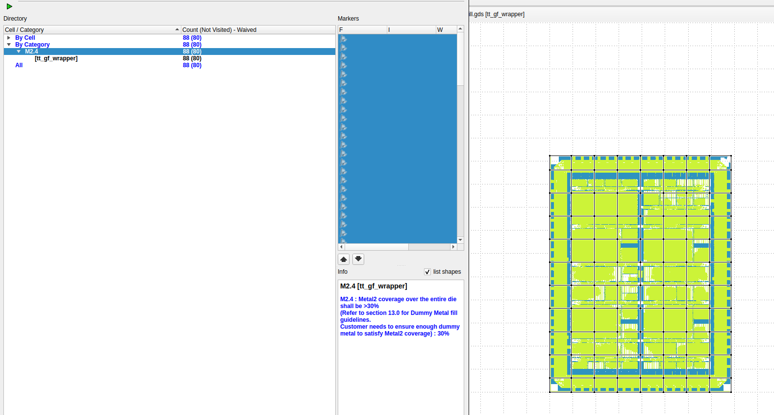
 1
1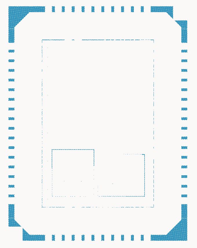
29.238749553369797
Metal2 layer 
 1
1dummy layer to drawing layer and be done with it. 1 1 Unfortunately, there's no easy way... 1
| ID | Project | Docker | Max Mem GB | Runtime Hrs | Date |
|---:|---------------------------------------------|--------|-----------:|------------:|------------|
| 48 | BreakingTTAPs | 0f9e5 | 11.09 | 13.67 | 2025-12-07 |
| 39 | FA25_Engn2912e_Saligane_Brown | 0f9e5 | 16.15 | 4.19 | 2025-12-06 |
| 9 | FABulous FPGA | 739cb | 14.41 | 3.02 | 13 | FazyRV Hachure | 739cb | 14.12 | 7.39 | 2025-12-03 |
| 32 | FOSSi open-source replacement for Z80 CPU | 0f9e5 | 14.82 | 4.28 | 2025-12-06 |
| 50 | FOSSi open-source replacement for Z80 CPU | 0f9e5 | 13.06 | 5.79 | 2025-12-07 |
| 28 | gf180mcu-jku-atbs-adc | 64e7f | 12.18 | 3.46 | 2025-12-05 |
| 29 | gf180mcu-jku-projects | 64e7f | 15.65 | 10.90 | 2025-12-05 |
| 45 | gf180mcu-project-trident-teststructure | 0f9e5 | 5.97 | 2.18 | 2025-12-07 |
| 6 | ISHI-KAI's Multiple Users Project | 739cb | 16.38 | 5.03 | 2025-12-02 |
| 41 | MOSbiusV3 | 0f9e5 | 7.66 | 2.61 | 2025-12-06 |
| 51 | ocd_sram_test | 0f9e5 | 5.57 | 3.24 | 2025-12-07 |
| 12 | Tiny Tapeout GF 0.2 | 739cb | 14.21 | 4.74 | 2025-12-03 |
| 11 | Tiny Tapeout GF 0p2 - Power Gated Variant | 739cb | 14.38 | 4.56 | 2025-12-03 |
| 19 | TinyQV - Crowdsourced Risc-V SoC | 64e7f | 6.11 | 4.85 | 2025-12-05 |
| 18 | TinyQV - Crowdsourced Risc-V SoC (0.5x1) | 0f9e5 | 9.71 | 8.56 | 2025-12-07 |
| 17 | TinyQV - Crowdsourced Risc-V SoC (1x0.5) | 0f9e5 | 13.11 | 7.92 | 2025-12-07 |evaluate_nets version vs the native antenna_check version ?evaluate_nets version vs the native antenna_check version ? put to put properties on the output shapes would also result in them being in the lyrdb. 1 1 1FP_IO_VLAYER to 'Metal4' ?FP_IO_VLAYER to 'Metal4' ? 1 1 1 1
1 1 1| ID | Project | Docker | Max Mem GB | Runtime Hrs | Date |
|---:|---------------------------------------------|--------|-----------:|------------:|------------|
| 48 | BreakingTTAPs | 0f9e5 | 11.09 | 13.67 | 2025-12-07 |
| 39 | FA25_Engn2912e_Saligane_Brown | 0f9e5 | 16.15 | 4.19 | 2025-12-06 |
| 9 | FABulous FPGA | 739cb | 14.41 | 3.02 | 13 | FazyRV Hachure | 739cb | 14.12 | 7.39 | 2025-12-03 |
| 32 | FOSSi open-source replacement for Z80 CPU | 0f9e5 | 14.82 | 4.28 | 2025-12-06 |
| 50 | FOSSi open-source replacement for Z80 CPU | 0f9e5 | 13.06 | 5.79 | 2025-12-07 |
| 28 | gf180mcu-jku-atbs-adc | 64e7f | 12.18 | 3.46 | 2025-12-05 |
| 29 | gf180mcu-jku-projects | 64e7f | 15.65 | 10.90 | 2025-12-05 |
| 45 | gf180mcu-project-trident-teststructure | 0f9e5 | 5.97 | 2.18 | 2025-12-07 |
| 6 | ISHI-KAI's Multiple Users Project | 739cb | 16.38 | 5.03 | 2025-12-02 |
| 41 | MOSbiusV3 | 0f9e5 | 7.66 | 2.61 | 2025-12-06 |
| 51 | ocd_sram_test | 0f9e5 | 5.57 | 3.24 | 2025-12-07 |
| 12 | Tiny Tapeout GF 0.2 | 739cb | 14.21 | 4.74 | 2025-12-03 |
| 11 | Tiny Tapeout GF 0p2 - Power Gated Variant | 739cb | 14.38 | 4.56 | 2025-12-03 |
| 19 | TinyQV - Crowdsourced Risc-V SoC | 64e7f | 6.11 | 4.85 | 2025-12-05 |
| 18 | TinyQV - Crowdsourced Risc-V SoC (0.5x1) | 0f9e5 | 9.71 | 8.56 | 2025-12-07 |
| 17 | TinyQV - Crowdsourced Risc-V SoC (1x0.5) | 0f9e5 | 13.11 | 7.92 | 2025-12-07 |  1
1 1
1
$add cell. synthesis is the job of taking these high-level concept cells and lowering them into concrete implementations. one way you can do that is with the techmap command, which takes in a "mapping" Verilog file, and replaces a cell with the contents of that mapping for the cell. the "different strategies" generally amount to passing a techmap file to map the cell however you want it before the default mapping is applied 1techmap to apply only on certain parts of the design. but this is, admittedly, somewhat fragile, and librelane doesn't really expose this I really need to dig into how these tools work more so I have a better intuition about what's going on
&mfs, aiger vs xaiger flops and nldm vs ccs at the bottom
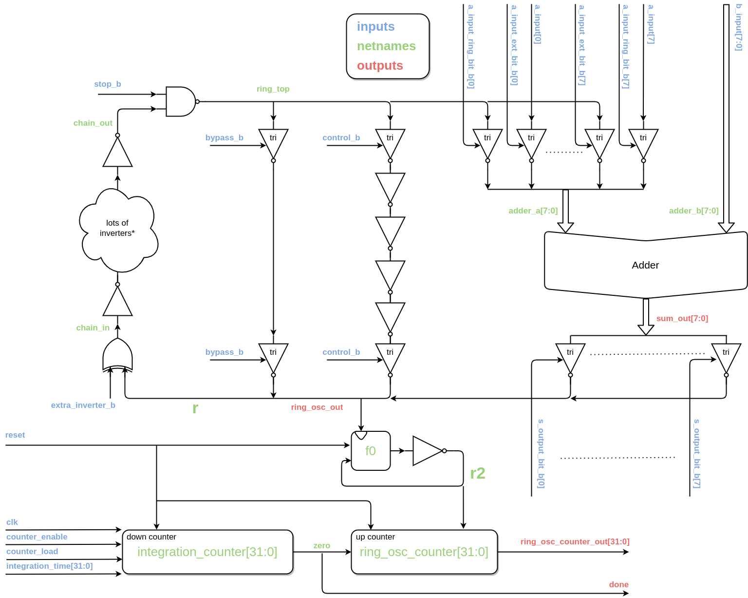 1
1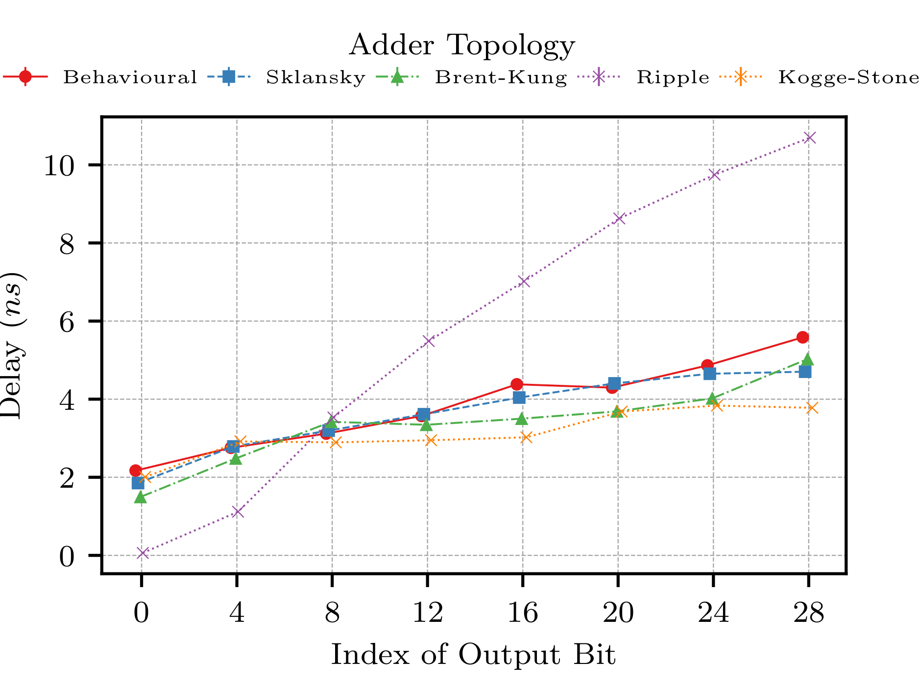 1 1 from: https://pubs.aip.org/aip/acp/article-pdf/1324/1/346/11503305/346_1_online.pdf
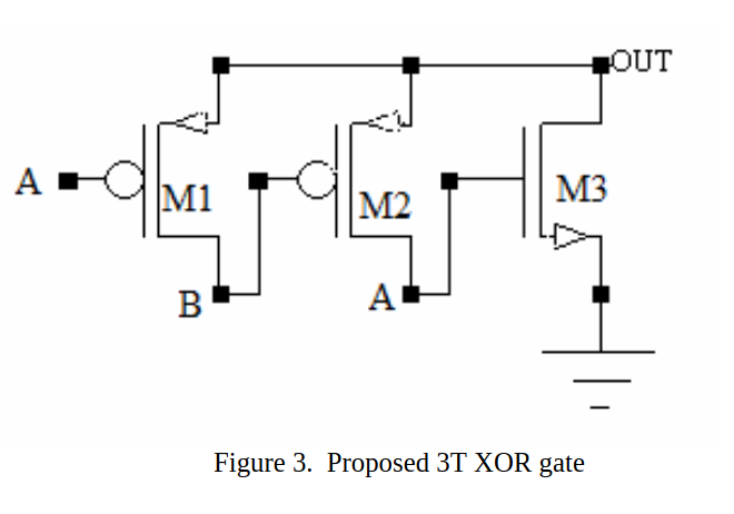 1
1module gf180mcu_as_sc_mcu7t3v3__dfsrtp_2(
input VPW,
input VNW,
input VDD,
input VSS,
input CLK,
input D,
input RN,
input SN,
output Q
);
reg state;
wire sr;
assign sr = ~(RN & SN);
assign Q = state;
always @(posedge CLK or posedge sr) begin
if (sr == 1'b1) begin
if (RN == 1'b0) begin
state <= 1'b0;
end else if (SN == 1'b0) begin
state <= 1'b1;
end
end else begin
state <= D;
end
end
endmodulemodule gf180mcu_as_sc_mcu7t3v3__dfsrtp_2(
input VPW,
input VNW,
input VDD,
input VSS,
input CLK,
input D,
input RN,
input SN,
output Q
);
reg state;
wire sr;
assign sr = ~(RN & SN);
assign Q = state;
always @(posedge CLK or posedge sr) begin
if (sr == 1'b1) begin
if (RN == 1'b0) begin
state <= 1'b0;
end else if (SN == 1'b0) begin
state <= 1'b1;
end
end else begin
state <= D;
end
end
endmodule module gf180mcu_as_sc_mcu7t3v3__dfsrtp_2(
input VPW,
input VNW,
input VDD,
input VSS,
input CLK,
input D,
input RN,
input SN,
output Q
);
reg state;
assign Q = state;
always @(posedge CLK or negedge RN or negedge SN) begin
if (RN == 1'b0) begin
state <= 1'b0;
end else if (SN == 1'b0) begin
state <= 1'b1;
end else begin
state <= D;
end
end
endmodule@ me.
 1
1run_drc.py in this case.run_drc.py in this case. (edited) 1
1 (edited)
module PopCount128 (
input [127:0] data,
output [7:0] count // 8 bits to hold from 0 to 128 (inclusive)
);
wire [43:0] bit0_stage1;
wire [15:0] bit0_stage2;
wire [ 5:0] bit0_stage3;
wire [ 1:0] bit0_stage4;
wire [41:0] bit1_stage1;
wire [13:0] bit1_stage2;
wire [ 4:0] bit1_stage3;
wire [ 1:0] bit1_stage4;
wire bit1_stage5;
Add128 ad0(.data(data), .sum(bit0_stage1), .carry(bit1_stage1)); // 42
Add44 add1(.data(bit0_stage1), .sum(bit0_stage2), .carry(bit1_stage2)); // 14
Add16 add3(.data(bit0_stage2), .sum(bit0_stage3), .carry(bit1_stage3)); // 5
Add6 add4(.data(bit0_stage3), .sum(bit0_stage4), .carry(bit1_stage4)); // 2
Add2 add5(.data(bit0_stage4), .sum(count[0]), .carry(bit1_stage5)); // 0.625
wire [63:0] pop64 = {bit1_stage1, bit1_stage2, bit1_stage3, bit1_stage4, bit1_stage5};
PopCount64 count64(.data(pop64), .count(count[7:1]));
endmodule$popcount() in combination with SYNTH_ADDER_TYPE: FA instead. (edited)data[0] + data[1] + ...? 1data[0] + data[1] + ...? FA/HA solution and worse than $popcount() for GF180.$popcount that I can find?$popcount that I can find? 3 1
1 1
1 1
1 1 1 Have a design ready that passed the 1.5.5 precheck on the platform. Currently running a slightly adapted version (improved timing) to see if it still passes. If not, can I just select the prior (successfully checked) version when pressing "Submit for Manufacturing" or do I have to re-run it?
 1
1 1 1 large demand, relatively expensive and hard to emulate correctly.
SID has bunch of analog components inside - amps, filters and DACs. All with pretty unique characteristics.
GF180 is prefect for such a replica! 1 large demand, relatively expensive and hard to emulate correctly.
SID has bunch of analog components inside - amps, filters and DACs. All with pretty unique characteristics.
GF180 is prefect for such a replica! 2
1 1 large demand, relatively expensive and hard to emulate correctly.
SID has bunch of analog components inside - amps, filters and DACs. All with pretty unique characteristics.
GF180 is prefect for such a replica! 1 large demand, relatively expensive and hard to emulate correctly.
SID has bunch of analog components inside - amps, filters and DACs. All with pretty unique characteristics.
GF180 is prefect for such a replica! 2
 Hi! I heard there are a bunch of cool projects trying to make combinational designs of AI inference models. That's something I've been thinking a lot about in the past years as well and I would love to know more about it and if there's any progress. (edited) 1
 1 1
1 1 ) 1 5 1 2







 ♂️
♂️