Guild icon
wafer.space Community
Information / general
Welcome to wafer.space - documentation at wafer.space github - buy at buy.wafer.space - archives at discord.wafer.space
Between 2026-06-30 11:59 p.m. and 2026-08-01 12:00 a.m.

Avatar
Avatar
tnt
Need a moderator .. @Leo Moser (mole99) / @Tim 'mithro' Ansell / @Andrew Wingate ?
Tim 'mithro' Ansell 2026-07-01 3:14 a.m.
Was that spam or something else?
👍 2
Avatar
It was spam
7:27 a.m.
❤️ 2
😍 2
Chips4Makers aka Staf Verhaegen started a thread. 2026-07-01 8:10 a.m.
Avatar
quick sanity check before I submit - Should I set the ID to something that's unlikely to clash?
10:15 a.m.
or is that set wafer.space side when the precheck is run?
Avatar
Leo Moser (mole99) 2026-07-01 10:24 a.m.
The precheck does not check it against the other IDs, but the platform should prevent you from choosing an existing ID. The precheck will update the ID macros in your design with your chosen ID.
Avatar
ah, cool.
11:27 a.m.
thank you
👌 1
Avatar
always_ff_rohan 2026-07-01 11:59 a.m.
@Tim 'mithro' Ansell When is the next shuttle run scheduled?
Avatar
I suspect a few weeks after this run has been delivered so people can examine a design and submit an updated version
2:21 p.m.
so about 2 weeks after Early Q4 2026 Bare dies and packaged parts shipped to customers
Avatar
Well at some point runs should be overlapping.
Avatar
Okay, the color NTSC signal generator is coming along really well. It looks like I will be able to generate all the colors, just really badly.
7:14 p.m.
If this works, it’ll make for an interesting single-IO video output option
7:15 p.m.
I’m also going to attempt PAL again, but expect that one to catastrophically break again
7:15 p.m.
I’m not good at making demos, so I’ll continue to just display test patterns
7:15 p.m.
Avatar
Avatar
Tholin
I’m not good at making demos, so I’ll continue to just display test patterns
just adapt one of the demo's that looks good and has a friendly license to your modulator's digital interface?
Avatar
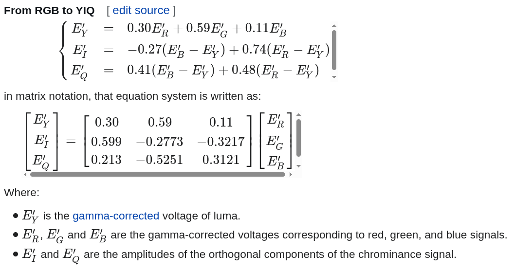
Not really a thing since a RGB to YIQ converter would be too many gates, I think
Avatar
just check it runs at less or equal resolution vs. your modulator's needs, and black box it as necessary
Avatar
Avatar
Tholin
Not really a thing since a RGB to YIQ converter would be too many gates, I think
ehhhh
9:24 p.m.
Avatar
Oops, took me until now to get a repo going https://github.com/AvalonSemiconductors/ws-submission-2026
Multi-project die. Contribute to AvalonSemiconductors/ws-submission-2026 development by creating an account on GitHub.
11:56 p.m.
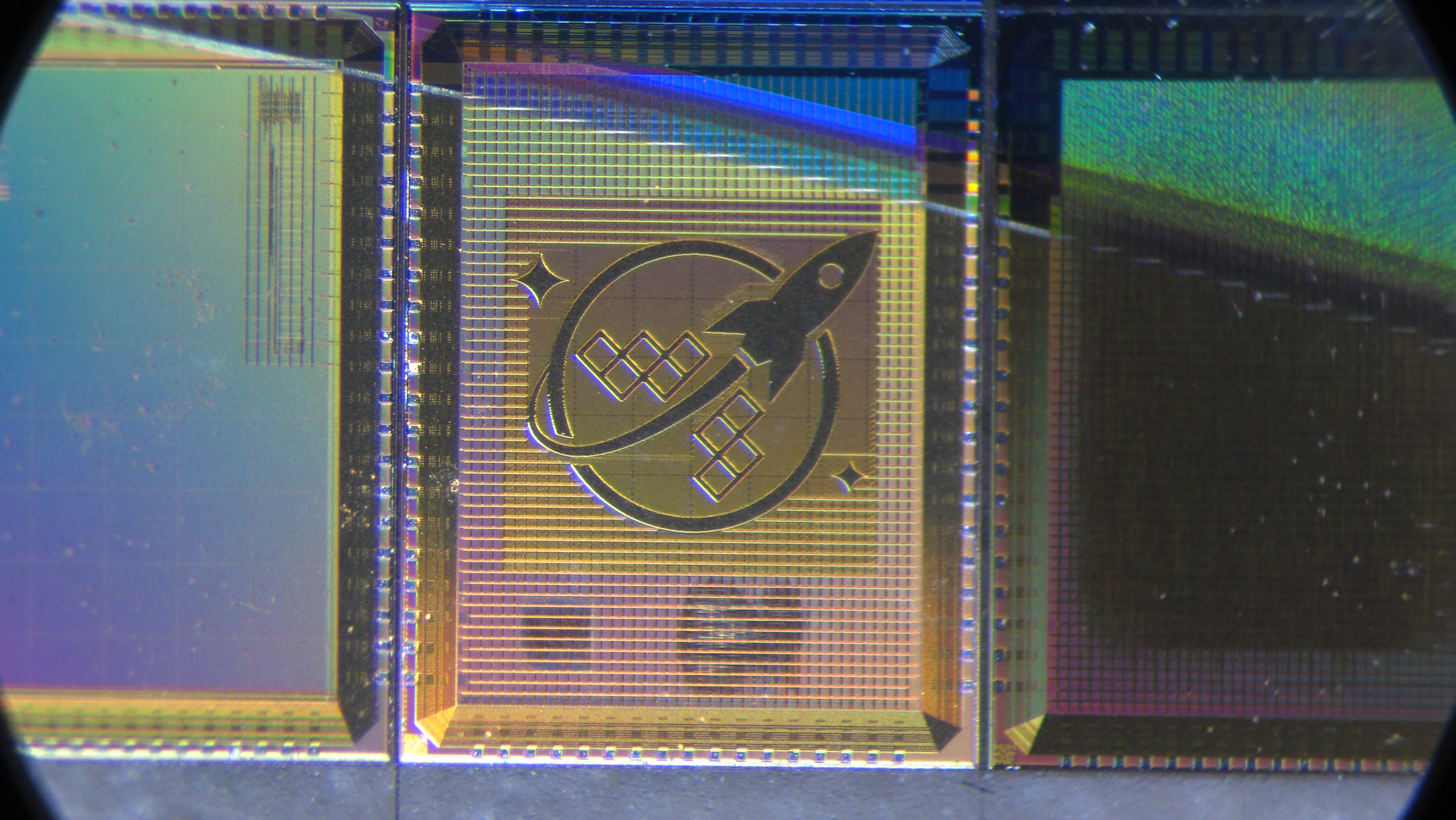
The functional components are actually done, leaving me with a comfortable two weeks to get the art ready. There is a block of free space on the die reserved for it.
Avatar
@Tim 'mithro' Ansell This is the project I wish to use to officially test my SCL, as well as my multi-project setup using my SCL. I’m also using the level-shifting IO pads, but for having a 5V IO voltage and 3.3V core voltage, which should be interesting. Also has layouts generated by my custom flow tool, analog layouts meant for 3.3V operation and, of course, a bunch of CPUs. Hoping to get a lot of mileage out of this one when it comes to testing things.
💜 2
Avatar
Avatar
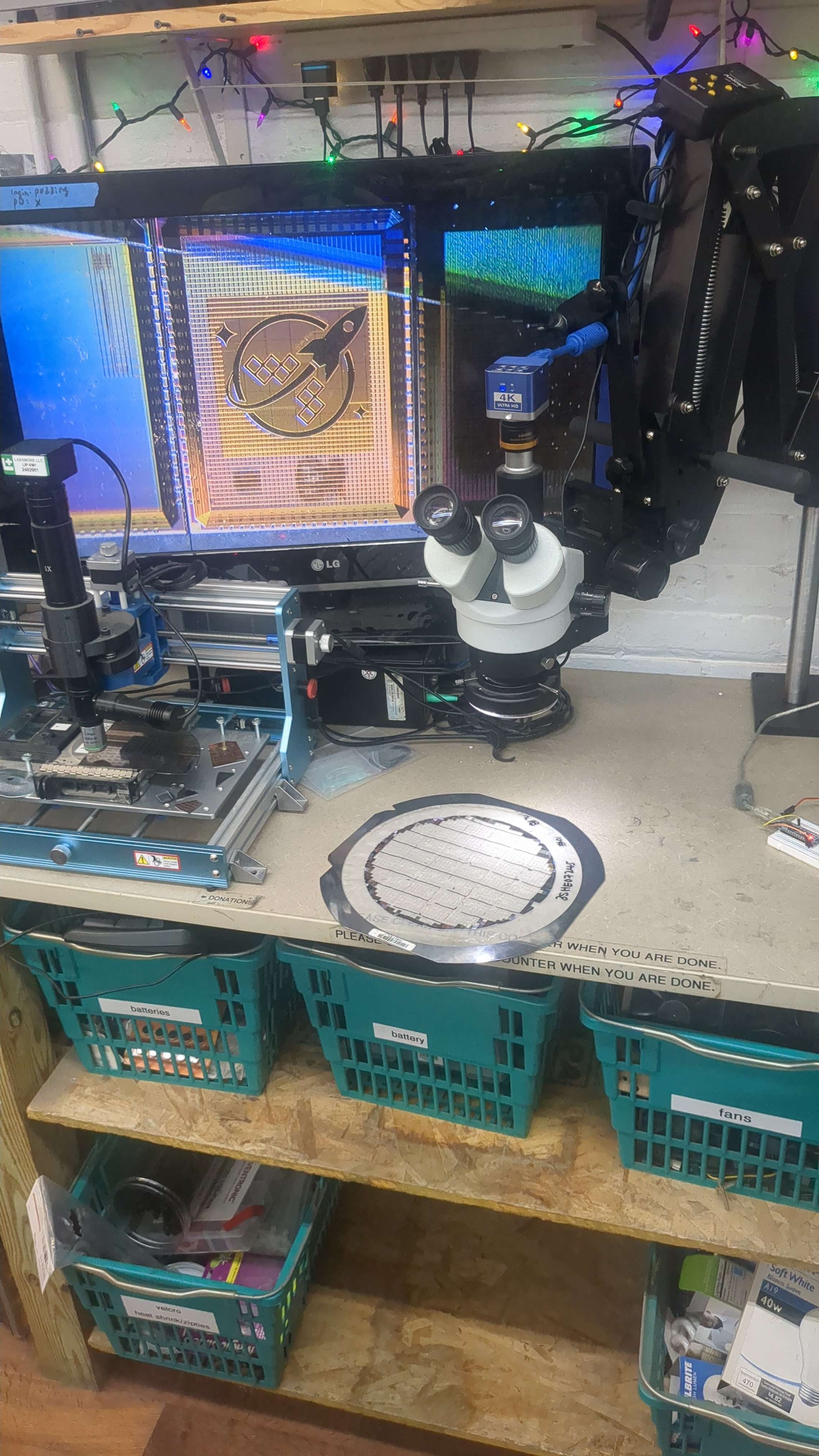
carlfk
Click to see attachment 🖼️
Nice setup
Avatar
I fixed the antenna violations so.... I’m actually done way ahead of deadline for once. This is highly unusual!
💯 2
3:39 p.m.
I’m just waiting for the art now
3:39 p.m.
I guess I’ll just sit here and wait for two weeks, then go get waffles?
Avatar
Leo Moser (mole99) 2026-07-02 4:02 p.m.
In case you're bored, a mux4 would be a great addition to your SCL 😉
Avatar
Avatar
Tholin
I’m not good at making demos, so I’ll continue to just display test patterns
is that in a repo? Ste ps1 guy loves color bars, loves analog and vga. might want to see what you are doing.
7:36 p.m.
oh look, a repo appeared!
Avatar
Avatar
Leo Moser (mole99)
In case you're bored, a mux4 would be a great addition to your SCL 😉
We will see. I am burnt out right now.
Avatar
Avatar
Tholin
I guess I’ll just sit here and wait for two weeks, then go get waffles?
In your position I'd think scripting together a flow of minting a lot of .nodeset's to cover all multistable/regenerative-feedback node voltages,
  • through probably the LVS tooling
  • and some minor singled-out-cell pseudo-DC-op-point sims where you'd start the transient with the regular DC op point initialization as always, then throw whatever waveforms against the inputs that are needed to bring the internal state into the target state, then just stop imposing a maximum step size and let the time integrator run for like an entire simulated minute or so, to then harvest the final state's node voltages from it (for the correct PVT corner! If it's too different one would risk the nonlinear solver potentially skipping across the forbidden band and deciding the flip-flop is actually better off in the opposite state; I do think in principle this could be solved by using the advanced continuation functionality:
the attached user guide's "Figure 8-3" "manual replication of MOSFET contonuation", amended with a 3rd conparam entry that happens after the mosfet:gainscale and mosfet:nltermscale entries, which will be essentially the output conductance of the current-type B-source which hard-forces the stateful digital logic cell's internal node voltage to the reference DC static voltage of the desired internal state of that particular cell, and is ramped from a very high conductance (strong but still sufficciently numerically behaved especially when it comes to transitioning out of the forced state; I'd probably just start with 1 siemens for any vaguely normal CMOS SCL internal nodes) down to literally 0 (which will have it be open-circuit at transient sim runtime). The parameter names legal to put into conparam are the same ones that are also legal to .STEP (the docs for how to casually do .STEP are far far easier to approach/read/understand than the fancy continuation stuffs). .options loca stepper=1 predictor=1 stepcontrol=1 could be semi-necessary to (properly/reliably) handle the effects of combinatorial loops through the (non-transparent at the time of the continuation solving!) flip-flops; if the continuation DC OP point solve ahead of the transient sim itself takes too long it'd be worth testing whether it's sufficciently robust with the tangent predictor 0 and thus the downgrade from the arc-length continuation stepper=1 to stepper=0. Though I guess maybe it has to do continuation over the output resistance and push that out to near-infinity in the continuation solve process (default is like 100 exa); the specified parameter constant value applicable outside of the special circumstances in which the LOCA does continuation on it, will need to be a sentinel (I'd suggest exact 0 or "anything negative"), as it shall be as non-interacting and as sparsified-away by the linear solver and all as possible (it's not a problem because the discintinuity doesn't happen while a non-linear solver tries to solve the system of equations and could have called the behavioral function with node voltages/branch currents far from anythign physical, because that's just discintinuos in a parameter, and that parameter doesn't change during any transient time integration...). Overall the idea I'm proposing is to use gate-level digital sim (post-techmapping (and any retiming and other such intrusive changes to the logic) verilog-sim basically 😄 ) to fast-forward to an interesting moment, snapshot all stateful state, map that against pre-computed DC op points of the cell library, use the LVS matching provisions to match that state to post-PEX SPICE node identifiers, emit a spice file to-be-.include'd full of those continuation-capable cell's-internal-node-forcing B-sources (test if things are faster when forcing combinatorial nets as well, or if the additional effort expended negates the faster convergence; .nodeset is likely cheaper for those though it's just not reliable), and start the .tran sim.
8:16 p.m.
(I can help later next week on the matter if you want; I'm just not at all deep enough int the digital simulation and LVS tooling side to handle that side of this simulation-type-marriage.)
Avatar
Goal IMO would be to (1) test some particularly questionable timing paths that came up in static timing analysis, (2) check if interaction between digital and analog aspects behaves sufficiently well/nicely to not be concerned about mixed-signal features being DOA due to oversights in the analog/digital interface specs, and (3) sanity check that at least normal interaction with any of the non-SCL parts of the chip (any of those) shows no signs of anythign shorting out or being close enough to shorting out to be nearly-equivalent. (I'm still mildy traumatized by how you (not-)handled the excessive current draw/heating of the Run1 die's DAC's buffers.) (The glitching of the video signal you've blamed on the lack of latching of the digital feed to the DACs is actually something I'd file under the above mentioned reason number 2, as it's one thing to accept the glitching if one is aware of it, but a whole nother thing to not have expected it/thought about it being possibly an issue.) (I'm not sure but depending on what you spit out of the NTSC modulator, like in theory there is place for the audio carrier, parts of the functionality are contingent on non-terrible artifacts/interference behavior, as e.g. audio will eventually hurt or at least give headaches if it's bad enough with some artifacts at least.)
Avatar
Avatar
namibj
In your position I'd think scripting together a flow of minting a lot of .nodeset's to cover all multistable/regenerative-feedback node voltages,
  • through probably the LVS tooling
  • and some minor singled-out-cell pseudo-DC-op-point sims where you'd start the transient with the regular DC op point initialization as always, then throw whatever waveforms against the inputs that are needed to bring the internal state into the target state, then just stop imposing a maximum step size and let the time integrator run for like an entire simulated minute or so, to then harvest the final state's node voltages from it (for the correct PVT corner! If it's too different one would risk the nonlinear solver potentially skipping across the forbidden band and deciding the flip-flop is actually better off in the opposite state; I do think in principle this could be solved by using the advanced continuation functionality:
the attached user guide's "Figure 8-3" "manual replication of MOSFET contonuation", amended with a 3rd conparam entry that happens after the mosfet:gainscale and mosfet:nltermscale entries, which will be essentially the output conductance of the current-type B-source which hard-forces the stateful digital logic cell's internal node voltage to the reference DC static voltage of the desired internal state of that particular cell, and is ramped from a very high conductance (strong but still sufficciently numerically behaved especially when it comes to transitioning out of the forced state; I'd probably just start with 1 siemens for any vaguely normal CMOS SCL internal nodes) down to literally 0 (which will have it be open-circuit at transient sim runtime). The parameter names legal to put into conparam are the same ones that are also legal to .STEP (the docs for how to casually do .STEP are far far easier to approach/read/understand than the fancy continuation stuffs). .options loca stepper=1 predictor=1 stepcontrol=1 could be semi-necessary to (properly/reliably) handle the effects of combinatorial loops through the (non-transparent at the time of the continuation solving!) flip-flops; if the continuation DC OP point solve ahead of the transient sim itself takes too long it'd be worth testing whether it's sufficciently robust with the tangent predictor 0 and thus the downgrade from the arc-length continuation stepper=1 to stepper=0. Though I guess maybe it has to do continuation over the output resistance and push that out to near-infinity in the continuation solve process (default is like 100 exa); the specified parameter constant value applicable outside of the special circumstances in which the LOCA does continuation on it, will need to be a sentinel (I'd suggest exact 0 or "anything negative"), as it shall be as non-interacting and as sparsified-away by the linear solver and all as possible (it's not a problem because the discintinuity doesn't happen while a non-linear solver tries to solve the system of equations and could have called the behavioral function with node voltages/branch currents far from anythign physical, because that's just discintinuos in a parameter, and that parameter doesn't change during any transient time integration...). Overall the idea I'm proposing is to use gate-level digital sim (post-techmapping (and any retiming and other such intrusive changes to the logic) verilog-sim basically 😄 ) to fast-forward to an interesting moment, snapshot all stateful state, map that against pre-computed DC op points of the cell library, use the LVS matching provisions to match that state to post-PEX SPICE node identifiers, emit a spice file to-be-.include'd full of those continuation-capable cell's-internal-node-forcing B-sources (test if things are faster when forcing combinatorial nets as well, or if the additional effort expended negates the faster convergence; .nodeset is likely cheaper for those though it's just not reliable), and start the .tran sim.
forgot to attach the file
Exported 40 message(s)
Timezone: UTC+0